24V
21
22
9
38
26 25 24 23 22 21 20 19 18 17 16 15 14 13 12 11 10 9 8 7 6 5 4 3 2 1
37 36 35
10 11 12
FOO126A
Ethernet Ext.1 Local Power A B Go
MAS 711Monitoring and Status
TD TDRD RD TD RD
Ext.2
Link LAN
19 7 1
20 18
14
17 16 13 8 5
3 15 4 62
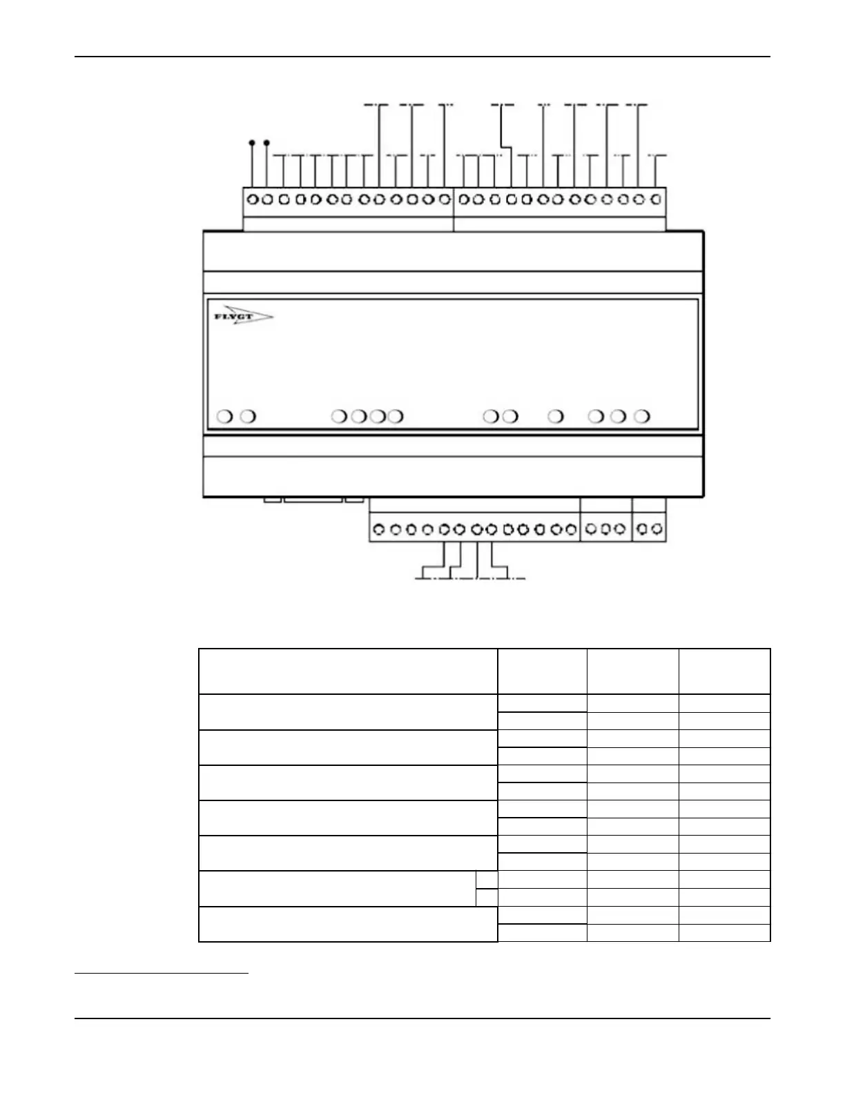
Figure 19: Connections at the MAS 711 base unit
This table shows how the conductors are connected to the different sensors.
Sensor Terminal
block
Conductor
number for 12-
lead cable
Conductor for
24-lead cable
Float switch in the stator housing
3
1 1 1
2
2 2
Float switch in the junction box
9 7 7
2
— —
Pt100 in the main bearing
4
3 3 3
4
4 4
Pt100 in the support bearing
37 — 17
38
— 18
Thermal switches or thermistors in the stator
5 5 5
6
6 6
CLS sensor in the oil housing +
33 — 19
–
34 — 20
Pt100 in the stator winding 1
19 8 8
4
— —
3
The leakage sensors in the stator housing and the junction box use the same terminal (terminal 2) on the terminal block.
4
The Pt100 sensor in the main bearing and the support bearing use the same terminal (terminal 4) on the terminal block
Installation
54 C3300/6x5, C/R3231, C3240, C3306, C3312, C3351, C3356, C3400, C3501, C3531, C3602, C3800 Installation,
Operation and Maintenance Manual