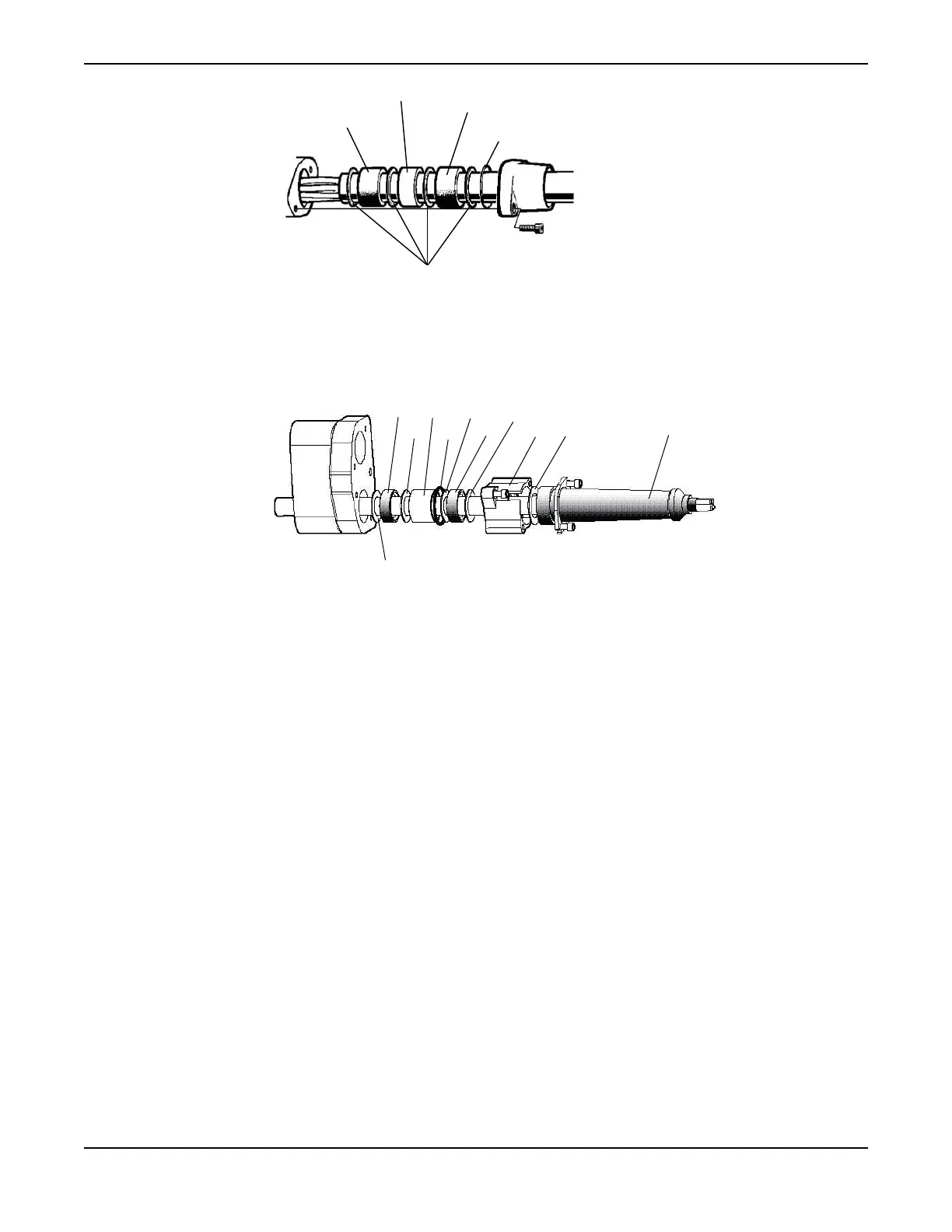
1. Seal sleeve
2. Spacer ring
3. Seal sleeve
4. O-ring
5. Washer
Figure 15: Drive units 605-775
1
2
3
4
5
6
7
8
9
10
11
1. Protective sleeve
2. Washer
3. Connection flange
4. Washer
5. Seal sleeve
6. Washer
7. O-ring
8. Spacer ring
9. Washer
10. Seal sleeve
11. Washer
Figure 16: Drive unit 805-995
b) Mount the protective rubber sleeve onto the cable where it leaves the junction box (connection
housing).
The rubber sleeve must have the correct size to give the correct compression around the cable.
c) Fasten the connection flange to the entrance flange.
Make sure that the seal sleeve is not misaligned with the rubber sleeve and that the entrance flange
supports the cable so that it cannot be excessively bent.
5. Connect the starter equipment:
a) Connect the power cable to the starter equipment according to the diagram in Power cable phase
sequence (page 51).
b) Connect the auxiliary cable to the starter equipment.
Power cable phase sequence
In the following figure, the triangle marked “L1,” “L2” and “L3” shows the phase sequence.
Installation
C3300/6x5, C/R3231, C3240, C3306, C3312, C3351, C3356, C3400, C3501, C3531, C3602, C3800 Installation,
Operation and Maintenance Manual
51