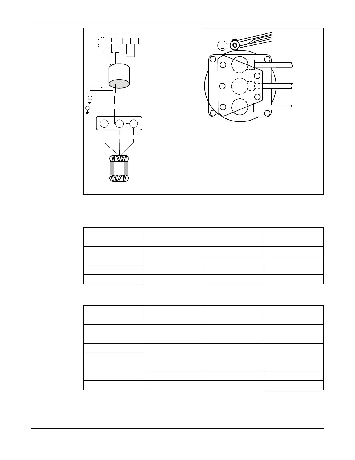
NTSCGE-
WTOEUS
L2 L3L1
GC
3~
V1
U1
W VU
L2
L1
L3
GC
GC
W1
Figure 39: Schematic diagram
Figure 40: Connection diagram
Cable bending radius, weight and diameter
This table shows the minimum bending radius, weight and outer diameter for SUBCAB
®
control cables.
Table 14: SUBCAB
®
control cables
Cable Minimum bending
radius in mm
Weight in kg/m Outer diameter,
minimum-maximum in
mm
12x1.5 mm
2
190 0.53 Ø 18.2–21.2
24x1.5 mm
2
250 0.90 Ø 24.9–28.9
S12x1.5 mm
2
300 0.78 Ø 29.9–31.0
S24x1.5 mm
2
350 1.59 Ø 33.0–37.0
This table shows the minimum bending radius, weight and outer diameter for SUBCAB
®
power cables.
Table 15: SUBCAB
®
power cables
Cable Minimum bending
radius in mm
Weight in kg/m Outer diameter,
minimum-maximum in
mm
4 G 16 mm
2
260 1.25 Ø 26.0–28.0
4 G 25 mm
2
320 1.9 Ø 32.5–34.5
4 G 35 mm
2
360 2.5 Ø 36.5–38.5
4 G 50 mm
2
410 3.4 Ø 41.0–45.0
4 G 70 mm
2
450 4.5 Ø 45.0–49.0
4 G 95 mm
2
500 5.8 Ø 54.0–58.0
4 G 120 mm
2
600 7.3 Ø 56.0–60.0
This table shows the minimum bending radius, weight and outer diameter for SUBCAB AWG power
cables.
Installation
C3300/6x5, C/R3231, C3240, C3306, C3312, C3351, C3356, C3400, C3501, C3531, C3602, C3800 Installation,
Operation and Maintenance Manual
65