Note that in all MFR-31CPU units the IP address of MFR-LAN1 is set to 192.168.1.11 and
that of PC-LAN1 to 192.168.0.13 as factory default. In all MFR-3100EX units the IP address
of MFR-LAN2 is set to 192.168.1.10 and that of PC-LAN2 to 192.168.0.12. To prevent IP
address overlap in a system, you need to change IP addresses of either unit.
Also note that desired IP addresses can be set for system devices according to your network
conditions.
Setup Procedure
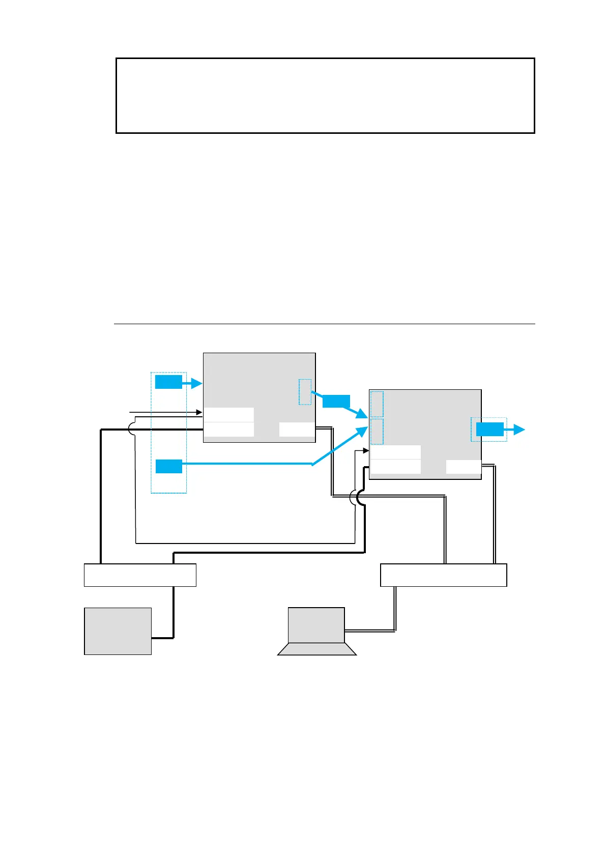
1) Connect all devices in the MFR system as shown in the figure in the previous page.
Power on the MFR-3100EX to be set as a Master, Remote Control unit and PC. Set the
IP addresses for the Remote Control unit (❶) and PC (❹). Power off the MFR-3100EX.
2) Power on another MFR-3100EX. Set the IP addresses (❺ and ❻) as shown in the
previous page.
3) Power on the Master MFR-3100EX.
4) Connect to the Master MFR-3100EX Web-based control and open the Build Setting
page. Check on Build Enable to enable the Main Unit Link feature.
See "Main Unit Link" in the Web-based Control Operation Manual.
3-2-2. Expanded Matrix System Example
The system example below connects two MFR-3100EX units to form a 96 x 32 virtual matrix.
◆ Setup Procedure
1) Connect two MFR-3100EX units, one by one, to the MFR system, referring to the previous
chapter for details on to setting network settings. Do not use the same IP address twice
in the system.
2) Turn on both MFR-3100EX power supplies. Connect BNC cables.
3) Connect to the Web-based Control of an MFR-3100EX and open the Build Setting page.
Check on Build Enable to enable the Main Unit Link feature.
See "Main Unit Link" in the Web-based Control Operation Manual.

 Loading...


