58
7. Serial / LAN Command Control
Up to 20 external devices can be connected to an MFR Main Unit (including MFR-GPI serial ports)
through LAN or serial interface.
7-1. Serial Interface
Crosspoint switchover and tally output can be controlled via the SERIAL port 1-4 on the MFR GPI.
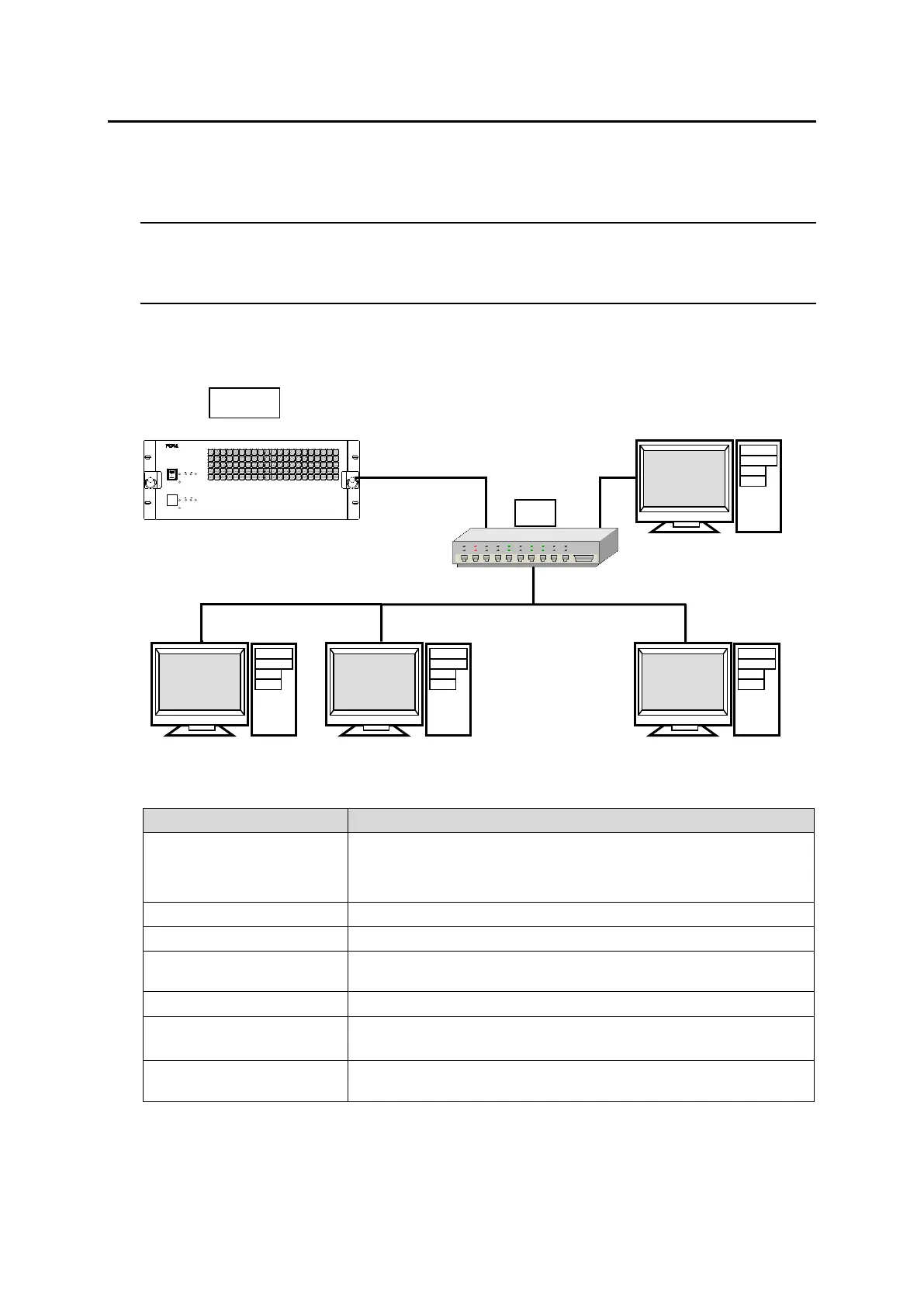
7-2. LAN Interface
The MFR Series main unit is able to connect to a third-party automatic control system via the RJ-
45 port (PC-LAN port). The TCP/IP communication protocol is supported. The control PC will be
the Client, and the MFR Series main unit will be the Server.
◆ Basic specifications
Primary side (PC-LAN CPU1) Default = 192.168.0.13
Secondary side (PC-LAN CPU2) Default = 192.168.0.12 *
(Subnet Mask = 255.255.255.0)
Setting range: 49152 to 65534 (Default: 23)
Wait before sending next command (Resend if the Echo is not
returned.)
TCP/IP, Control PC: Client, MFR-3100EX: Server
The protocol below uses ASCII code.
Crosspoint remote control and Audio remote settings protocols
(in ASCII code)
* In a redundant CPU configuration, the Client should be connected to both the primary side
(PC-LAN CPU1) and the secondary side (PC-LAN CPU2) and send control commands to both.
Normally, the secondary side can only be connected and does not respond to commands, but
if an error occurs and the CPU switches to the secondary side, the secondary side will accept
control and respond.
POWER 1
ON
OFF
ALARM
CPU2
ACTIVE
CPU1
REF INPOWER
POWER 2
ON
OFF
ALARM
CPU2
ACTIVE
CPU1
REF INPOWER
ROUTING SWITCHER
MFR-3100EX

 Loading...


