Technology
Components, Connections, and Dimensions
Page 32
M0930207 I
❒ Wire the connections in accordance with the schematic diagram.
Wire the connections in accordance with the circuit diagram.
For circuit diagrams see operating instructions for "Lambdatronic
P 3200."
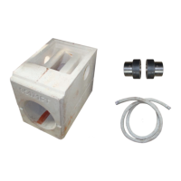
Remove screws above and below wire pass-through.
Mount the included electrical box.
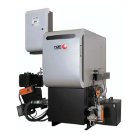
Pull the Fan cables through the lower cable duct to the electrical
boards at the front side of the boiler.
Lay the Fan cables in the wiring duct.
Plug the Fan cables into the “ID Fan” socket at the core module.
Pull the power feed (supply) wires and circulator power connections
through the lower cable duct to the electrical boards at the front side
of the boiler.