Technology
Components, Connections, and Dimensions
Fröling Heizkessel- und Behälterbau Ges.m.b.H, Industriestrasse 12, A-4710 Grieskirchen Page 33
Tel +43 (0) 7248 606-0 Fax +43 (0) 7248 606-600 info@froeling.com www.froeling.com M0930207
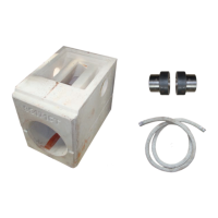
Complete the main connections (L1, L2, N, PE).
Plug the circulator(s) into “pump 1 and pump 2” sockets on the
Hydraulic System Module board.
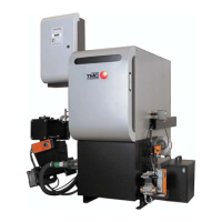
⇨ See "Temperature Sensors” [page 52]
Pull any temperature sensor cables through the upper cable duct
(try to keep high and low voltage wires separated).
Plug temperature sensors into sockets labelled “Sensor 1...6”.
⇨ See "Temperature Sensors” [page 52]
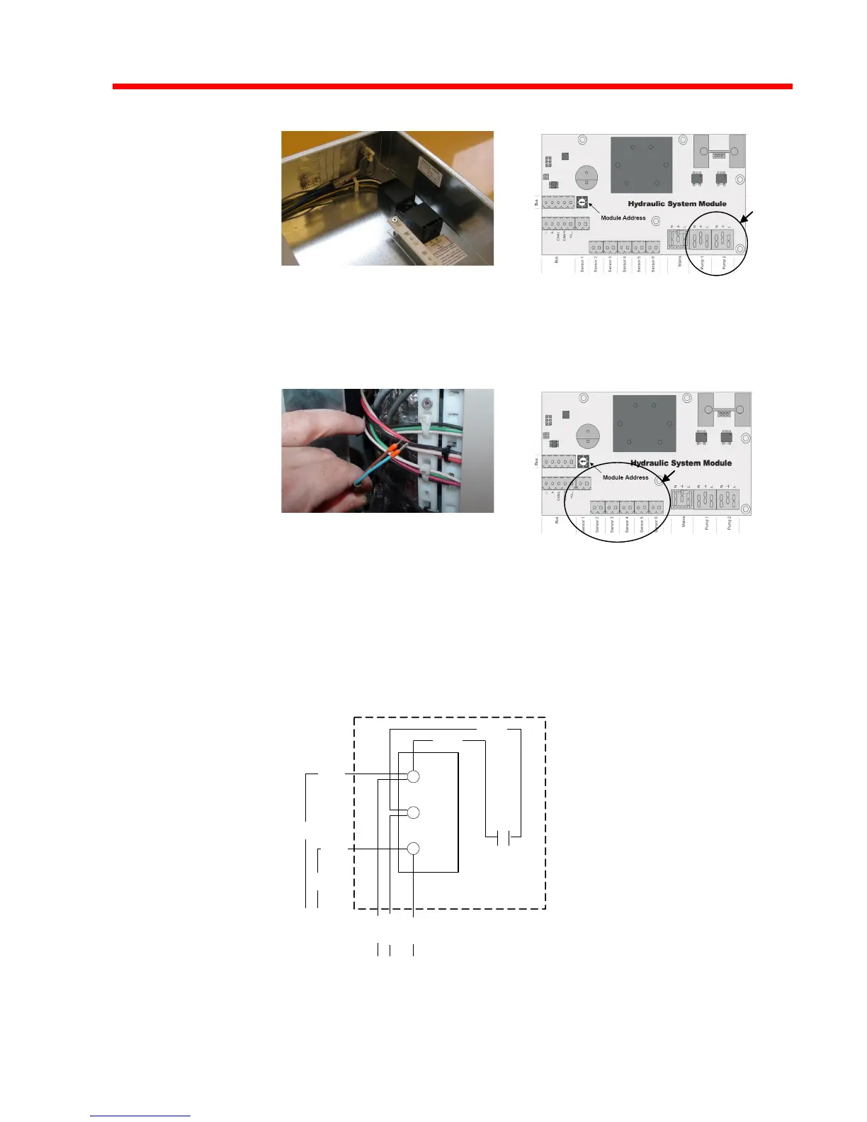
Wire Connections at Fan
U1
V1
W1
Capacitor
2
1
BLK
WHT
BLK
Incoming
From Core
Module
Red
White
BLK
Fan
Connections
WHT
Cover on Fan Housing