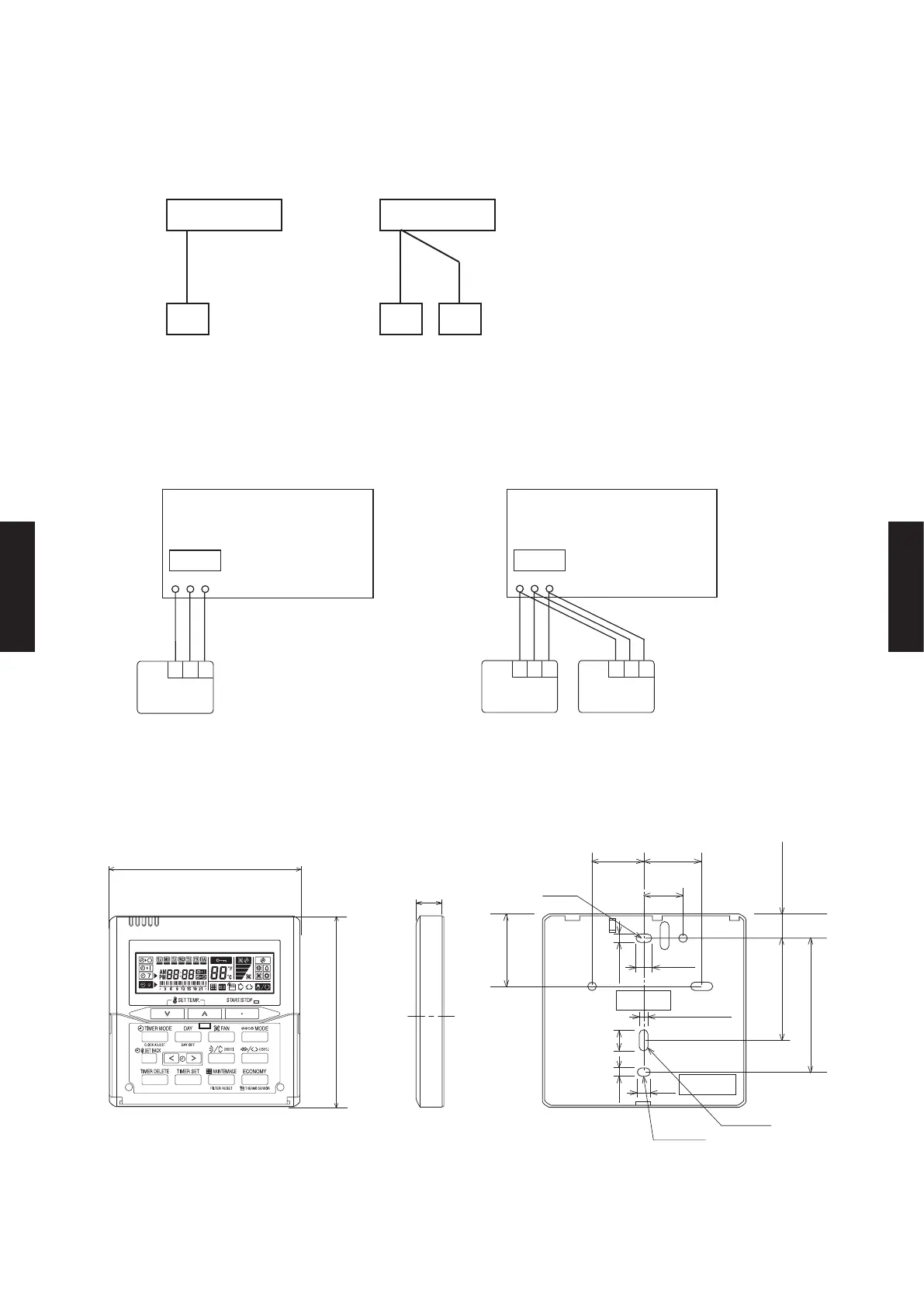
SYSTEM DIAGRAM
z
1 remote controller
ELECTRICAL WIRING
z
1 remote controller
DIMENSIONS
z
2 remote controllers
z
2 remote controllers
Master Slave
A B C
Indoor unit Indoor unit
Remote controller Remote controllers
A , B , C : Remote controller cable.
Refer to chapter 6. 4-4 for detail
specications.
A ≤ 1,640 ft. (500 m) ; B+C≤ 1,640 ft. (500 m)
REMOTE
CONTROLLER
1 2 3
1 2 3
Master
Slave
1 2 3
1 2 3 1 2 3
REMOTE
CONTROLLER
Remote controller Remote controllers
1 (RED) : 12 V
2 (WHITE) : Signal
3 (BLACK) : COM
3-5/16 (83.5)
5/8 (15.3)
2-1/2 ( 63.5)
Hole
1-13/16 (45.3)
3/16 (4.5)
3/8 (9)
1/2 (12.5)
Hole x 2
Hole x 3
3/16 (4.5)
3/16 (4.5)
1/4 (6)
7/8 (23)
4-3/4 (120)
11/16 (18)
4-3/4 (120)
1-3/16 (30) 1-5/16 (33.5)
Front View Side View Rear View
Unit : in. (mm)
- (05 - 66) -
CONTROL
SYSTEM
CONTROL
SYSTEM

 Loading...


