Case 2: For polar 3 wire
Modify the cable as per below methods.
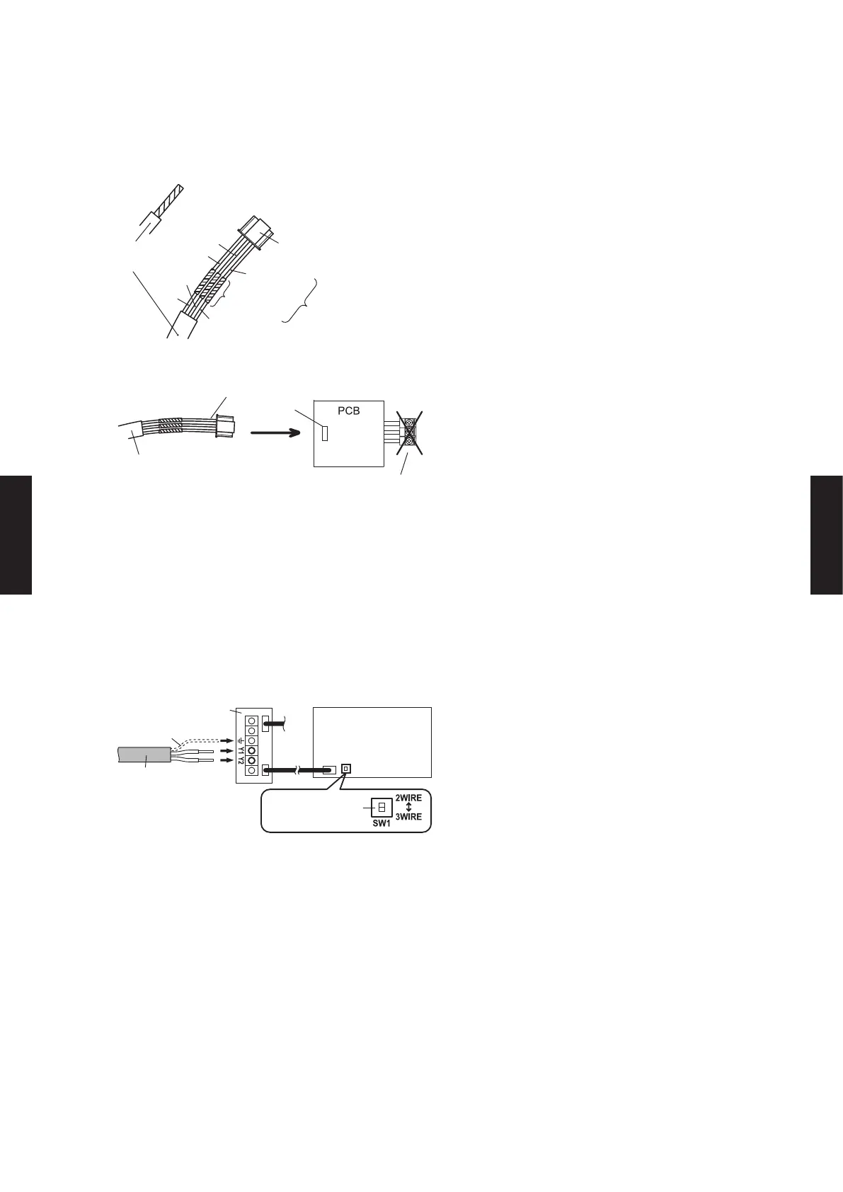
Use a tool to cut o the terminal on the end of the remote controller cable, and then
remove the insulation from the cut end of the cable as shown in Fig. 1.
Connect the remote controller cable and connecting cable as shown in Fig. 2.
Be sure to insulate the connection between the cables.
Remote
controller cable
Insulated
connection
Red
White
Connector
White
Black
Connecting
cable
Fig.1 Fig.2
Red
Black
Connect the remote controller cable to the connecting cable, and insert it to the connector.
Terminal block
to outdoor unit /
power supply
Connector
Indoor unit
Connecting cable
Remote controller cable
When the board has the 2WIRE/3WIRE DIP switch on it, set it to 3WIRE.
For how to set, see “Case 1: For non-polar 2 wire”.
z
(2) When connecting to the exclusive terminal block
Connect the end of remote controller cable directly to the exclusive terminal block.
If there is the 2WIRE/3WIRE switch on the PC board of the indoor unit, set it to match the
connection method of the connected remote controller cable.
Example) Connection of non-polar 2 wire
Terminal block
Functional earthing
(If necessary)
Set to “2WIRE” the
DIP switch (SW1)
Indoor unit
PC board
Remote controller
cable
* Layout of terminal block and
PC board is varies, depending
on the type of indoor unit.
- (05 - 177) -
CONTROL
SYSTEM
CONTROL
SYSTEM

 Loading...


