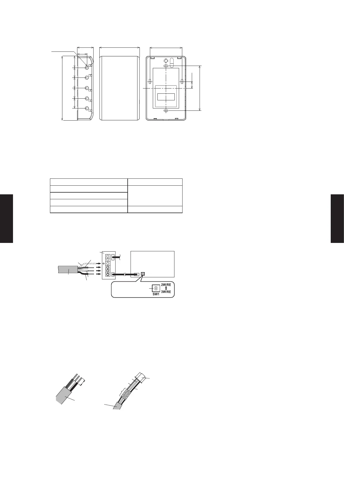
DIMENSIONS
Unit: in. (mm)
2-15/16 (75)1-3/16 (30)
4-3/4 (120)
13/16
(21)
3/4
(19.5)
3/4
(19.5)
3/4
(19.5)
3/4
(19.5)
11/16 (18)
2-3/8 (60)
3-5/16 (83.5)
1/2 (12.5)
5 - ø1/4 (7)
Left view Front view Rear view
INSTALLATION
z
Connection Pattern
NOTE:
Connection pattern is dierent for dierent indoor unit types.
Indoor unit types Connection Pattern
All Cassette type
Pattern A
All Duct type
All Ceiling type
Wall Mounted type Pattern B
z
Pattern A
Connect the end of remote controller cable directly to the exclusive terminal block.
Set the DIP switch (SW1) to "3WIRE" on the PCB of the indoor unit.
* Layout of terminal block and
PCB is varies, depending
on the type of indoor unit.
Terminal block
Functional earthing
(If necessary)
Remote controller
cable
Set to "3WIRE" the
DIP switch (SW1)
Indoor unit
PCB
Y1
Y2
Y3
Black
White
Red
NOTE:
The equipment may fail if it is connected to the outdoor unit or the power supply
terminal block.
z
Pattern B
1) Use a tool to cut o the terminal on the end of the remote controller cable, and then remove
the insulation from the cut end of the cable as shown in Fig. 1. Connect the remote controller
cable and connecting cable as shown in Fig. 2. Be sure to insulate the connection between
the cables.
Remote
controller cable
Insulated
connection
White
Black
13/16 in. (20 mm) Red
Connecting
cable
2.giF1.giF
- (05 - 182) -
CONTROL
SYSTEM
CONTROL
SYSTEM

 Loading...


