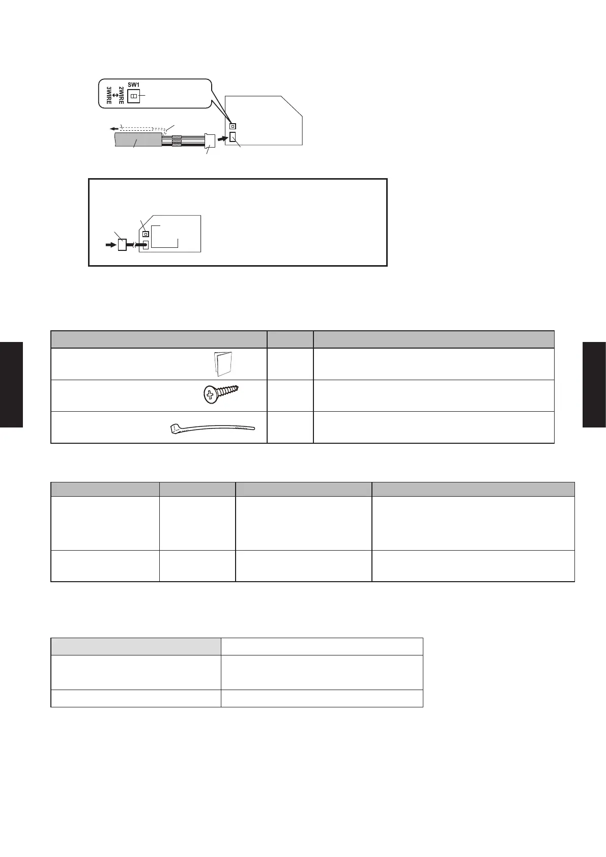
2) Connect the remote controller cable to the connecting cable, and insert it to the connector.
Set the DIP switch (SW1) to "3WIRE" on the PCB of the indoor unit.
Indoor unit
PCB
Remote controller
cable
Connecting cable
Connector CNC01
(onboard)
Connect to earth
(ground) screw
Functional earthing
(If necessary)
Set to "3WIRE" the
DIP switch (SW1)
* Layout of Connector and PCB varies, depending on the
type of indoor unit
Connector
(adapter)
SW1
Indoor unit
PCB
PACKING LIST
Name and shape Quantity Application
Installation manual 1
Screw
(M4 × 16 mm)
2 For installing the external switch controller
Cable Tie 5 For securing controller cable.
WIRING SPECIFICATIONS
Use Size Wire type Remarks
Remote controller
cable
22AWG
(
0.33
mm
2
)
Polar 3core
Use sheathed PVC cable or shielded
cable in accordance with the regional
cable standard.
External input /
output cable
22AWG
(
0.33
mm
2
)
Polar 2core, Twisted pair
Use shielded cable in accordance with
the regional cable standard.
SPECIFICATIONS
Power supply DC 12 V
Dimensions [H × W × D]: in. (mm)
4-3/4 × 2-15/16 × 1-3/16
(120 × 75 × 30)
Weight: lbs. oz. (g) 4 oz. (100)
- (05 - 183) -
CONTROL
SYSTEM
CONTROL
SYSTEM

 Loading...


