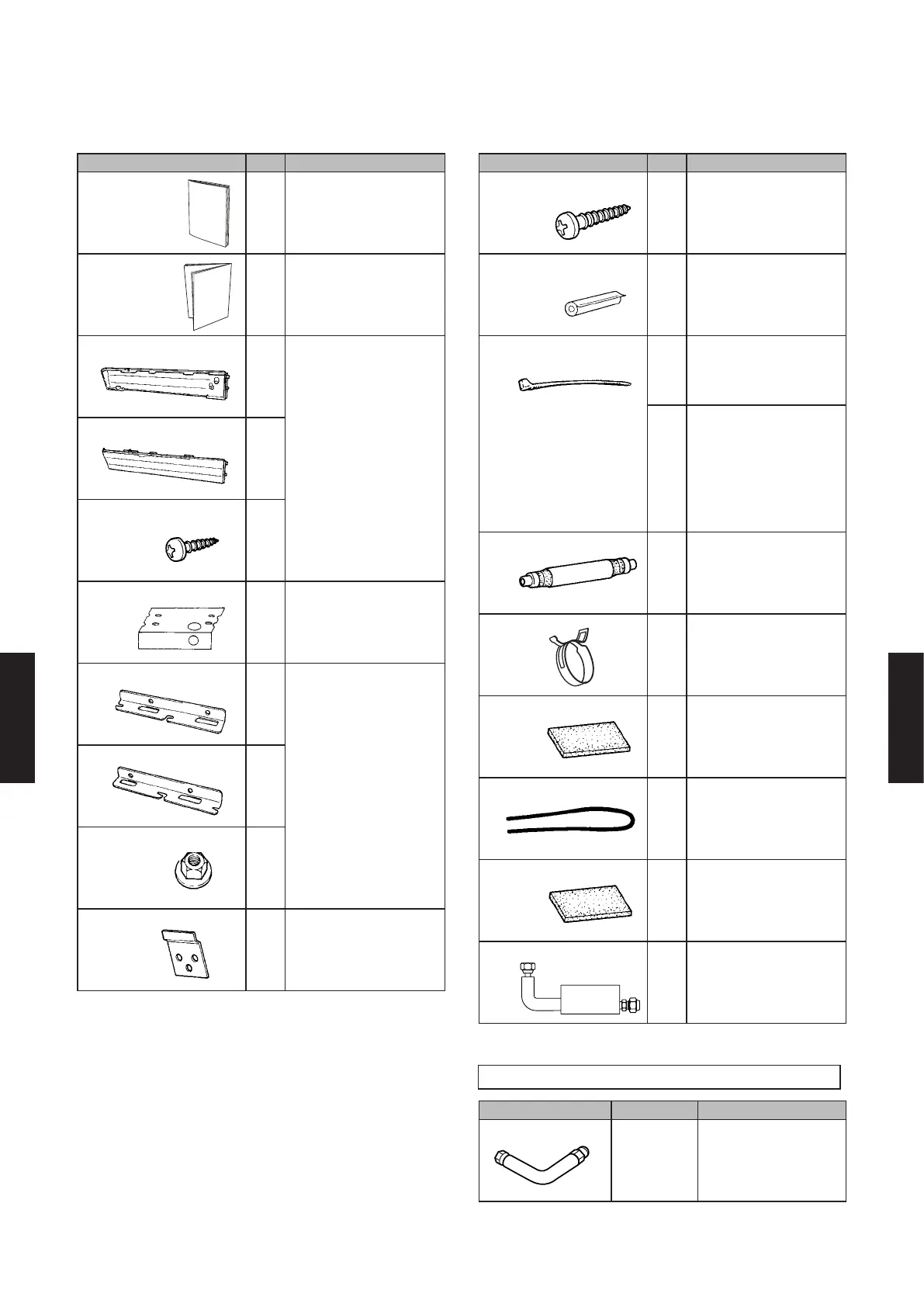
FLOOR / CEILING TYPE
Name and shape Q'ty Application
Operating
manual
1
Installation
manual
1
Cover plate (left)
1
Cover plate (right)
1
Tapping screw
2
Installation template
1
For positioning the
indoor unit
For under ceiling type
Bracket (left)
1
For suspending the
indoor unit from ceiling
Bracket (right)
1
Special nut
4
Wall bracket
2
For suspending the
indoor unit on the wall
Name and shape Q'ty Application
Tapping screw
6
For xing the wall
bracket
Pipe Insulation
2
For indoor piping
connection
Cable Tie(s)
Large
4
For securing the
refrigerant connection
pipes.
Me d i um
3
For securing the power
supply, transmission
cable and remote control
cable. Do not run power
cable and transmission
cable together, electrical
interference will cause
communication errors.
Drain hose
1
For connecting drain
hose.
Hose band
1
For installing drain hose
Drain hose insulation
1
Adhesive type
3-15/16 x 8-21/32 in.
(100 x 220 mm)
VT wire
1
For xing the drain hose
L=11-1/32 in. (280 mm)
Insulation (hose)
1
Adhesive type
6-5/16 x 4-11/32 in.
(160 x 110 mm)
Silencer pipe
1
Connect the silencer
pipe to the small (Liquid)
pipe
OPTIONAL PARTS
Name and shape Part No. Application
Auxiliary pipe
9374714025
For indoor side pipe
joint (For AB18, AB24)
- (06 - 76) -
SYSTEM
DESIGN
SYSTEM
DESIGN

 Loading...


