Pos. Print Description
25 M.2 SSD1 M.2 slot 1
26 M.2 SSD2 M.2 slot 2
27 SERIAL Connector for optional serial interface
Onboard indicators and controls
CPU
Slot 2
Slot 1
PWD CLR
RCVR
1 2
external connectors
LAN 1
LAN 1
Management
LAN
VGA
Shared LAN 2
USB 2.0
USB 2.0
USB 3.1
Gen 2
DIMM 2A
DIMM 1A
DIMM 2B
DIMM 1B
Micro
SD
FAN1
FAN2
SSD2
M.2
M.2
SSD1
Battery
TPM
Slot 3
FAN3
FAN4
iRMC
S5
JP8
PWR1
Front
Panel2
Front USB
Front Panel1
PWR2
PWR3
P30
HDD LED
ROC
PWR4
INDICATE
CSS
SATA
ODD
Front VGA
OOB
Intel
i210
Service
LAN
USB 1
SATA
0-3
PWR MAIN
PC98
SERIAL
Reset
Intel
C246
FAN5
USB 3.1
Gen 2
Intel
i210
F
F
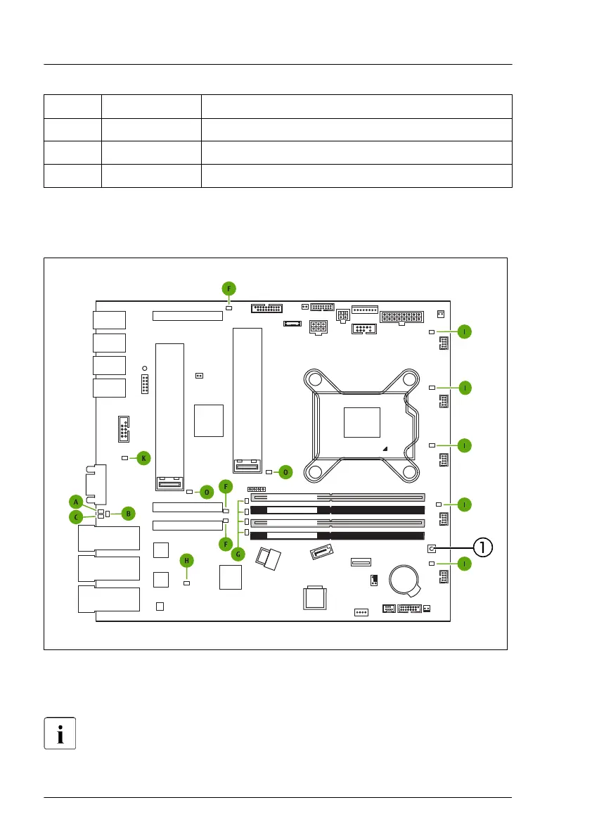
Figure 239: Onboard indicators and indicate CSS button
1 Indicate CSS button
LEDs A, B and C are visible from outside on the server rear. All other
LEDs are only visible if the server cover has been opened.
Appendix A
344 Upgrade and Maintenance Manual RX1330 M4

 Loading...