488
Upgrade and Maintenance Manual TX2560 M2 / RX2560 M2
System board and components
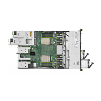
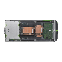
Figure 363: Removing the system board
Ê
Use both hands to lift the system board carefully out of the chassis in a slight
angle. Thereby you pull the connectors out of the connector panel.
V CAUTION!
Always take the system board with both hands!
Never lift the system board one-sided or at a heat sink, because the
solder connections between the socket and the system board come
under tension and increase the risk of damage and malfunction!
Don’t damage the EMI springs which are essential to comply with
applicable EMC regulations and satisfy cooling requirements and fire
protection measures.
Ê
Place the removed and the new system board on an antistatic surface.
Ê
Remove the TPM as described in section "Removing the TPM" on page 467.
14.7.1.3 Installing the new system board
Ê
Check the settings on the new system board (see section "Onboard
settings" on page 565).
Ê
Insert the system board by holding it at a slight angle. Slide the connectors
into the connector panel (see figure 363 on page 488).
 Loading...