2-46 ALPS Advanced Line Protection System
GE Power Management
2.3 PROTECTION SETTINGS 2 CALCULATION OF SETTINGS
2
1840: DELTAVBLK - Block Synch Check by DELTAV
DELTAVBLK can be set to YES or NO and establishes whether the synchronism check function is allowed to operate. Set
DELTAVBLK = YES to block the synchronism check function, otherwise set DELTAVBLK = NO.
2.3.21 NONCRIT_AL
Up to eight of the signals listed in the Index Tables given at the end of this section can be used to produce a non-critical
alarm signal (Index Number 52). This signal, when produced, will always be reported as an event and it can also be pro-
grammed to drive one of the output relays if an external alarm is required.
Set these Protection Settings to one of the available Index numbers given in the Table 2–10: INDEX NUMBERS –
SCHEME, RECLOSER, & PROGRAMMABLE LOGIC on page 2–52.
2.3.22 OUTPUTS
All 24 output contacts (Protection Settings 2001 to 2024) are configurable. They can be driven by any one of the functions
as described by an index number provided in the Tables at the end of this section. Each of the contacts has a default setting
(see Table 2–11: PROTECTION SETTINGS GUIDE on page 2–57). The default settings are established through an Xpres-
sion Builder file that is downloaded in the ALPS at the factory. The settings can be changed by modifying the logic via
Xpression Builder, ALPS-Link, or through the keypad. Note that any index number settings changed through the keypad or
ALPS-Link will be reflected in the configurable logic file, while any settings changed through the configurable logic will be
reflected in the settings file.
If other than the default setting is to be used, change the configurable logic or select an index number reflecting the function
by which the contact is to be driven.
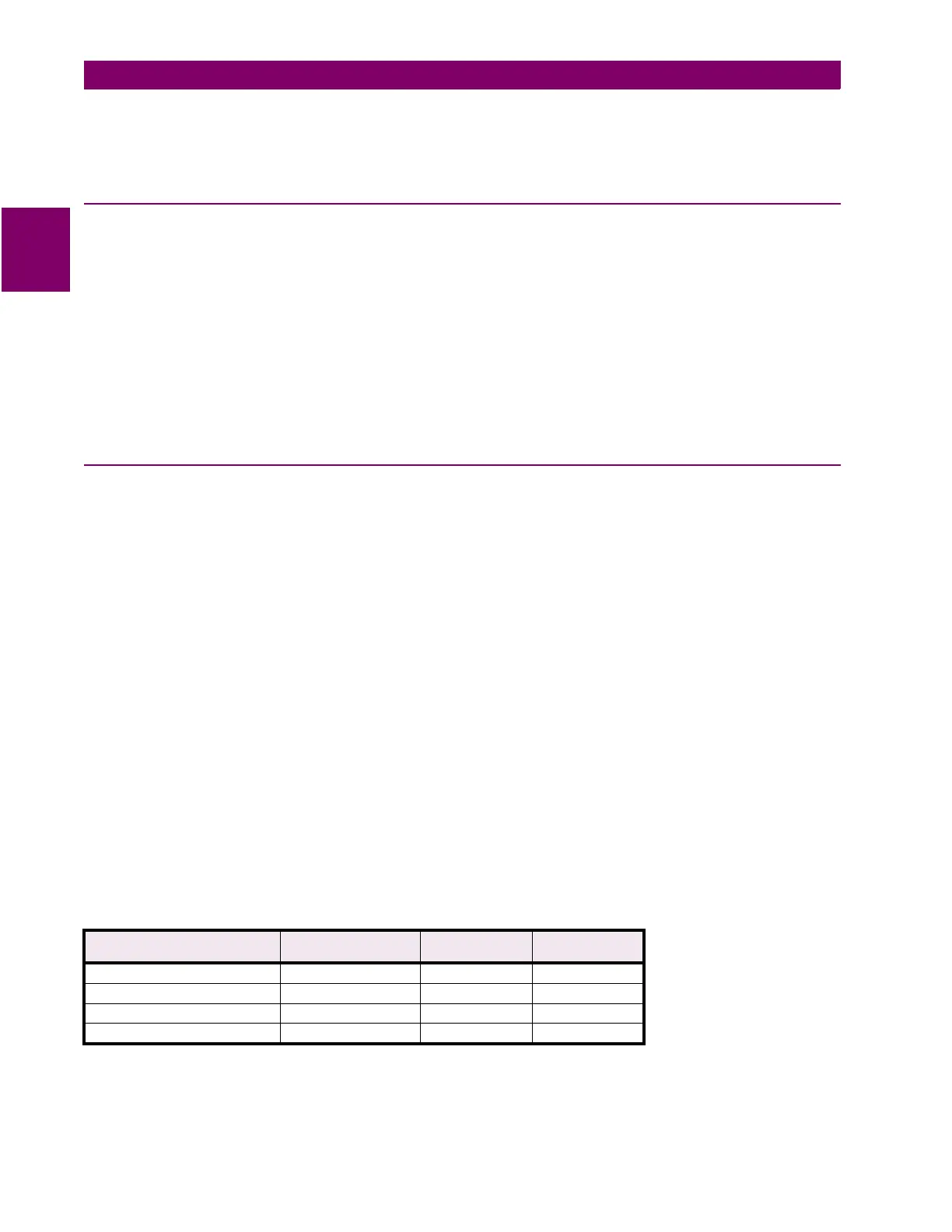
The following contact output assignments are recommended when the phase identified channel scheme (HYBRIDP) is
used. Note that KT3 and KT4 only need to be assigned for the four channel scheme.
1901: NCAIN1 - Non-Critical Alarm Input #1 1902: NCAIN2 - Non-Critical Alarm Input #2
1903: NCAIN3 - Non-Critical Alarm Input #3 1904: NCAIN4 - Non-Critical Alarm Input #4
1905: NCAIN5 - Non-Critical Alarm Input #5 1906: NCAIN6 - Non-Critical Alarm Input #6
1907: NCAIN7 - Non-Critical Alarm Input #7 1908: NCAIN8 - Non-Critical Alarm Input #8
2001: T1 - T1 Contact 2002: T2 - T2 Contact 2003: T3 - T3 Contact
2004: T4 - T4 Contact 2005: T5 - T5 Contact 2006: T6 - T6 Contact
2007: A1 - A1 Contact 2008: A2 - A2 Contact 2009: A3 - A3 Contact
2010: A4 - A4 Contact 2011: A5 - A5 Contact 2012: A6 - A6 Contact
2013: A7 - A7 Contact 2014: A8 - A8 Contact 2015: A9 - A9 Contact
2016: A10 - A10Contact 2017: A11- A11 Contact 2018: A12 - A12 Contact
2019: C1 - C1 Contact 2020: C2 - C2 Contact 2021: KT1 - KT1 Contact
2022: KT2 - KT2 Contact 2023: KT3 - KT3 Contact 2024: KT4 - KT4 Contact
Note: Settings 2005, 2006, and 2015 to 2018 are for Single Phase Tripping models only.
Table 2–8: OUTPUT ASSIGNMENT FOR HYBRIDP SCHEME
CONTACT OUTPUT
ASSIGNMENT
DESCRIPTION INDEX # MNEMONIC
2021:
KT1
- KT1 Contact Key Channel 1 39 KEY1
2022:
KT2
- KT2 Contact Key Channel 2 40 KEY2
2023:
KT3
- KT3 Contact Key Channel 3 53 KEY3
2024:
KT4
- KT4 Contact Key Channel 4 54 KEY4