GE Power Management
ALPS Advanced Line Protection System B-1
APPENDIX B B.1 MODBUS INTRODUCTION
B
APPENDIX B MODBUSB.1 MODBUS INTRODUCTION B.1.1 DESCRIPTION
This appendix describes the functional specifications/memory map of the Modbus RTU protocol interface for the ALPS
Advanced Line Protector System revision A (ALPS-A). The specifications cover Modicon Modbus application messages
supported by the ALPS interface software module.
The ALPS relay provides the user interface to configure the Modbus communications parameters. The Modbus device
address and the Baud Rate for RS485/RS232 port are configurable from the MMI of the ALPS.
There will be a delay before the ALPS is ready to answer Modbus requests from the Modbus master on power up. This is
due to internal data and baud rate synchronized tasks to be performed. Device address changes and baud rate changes
will affect the operation of the device once the device is communicating.
B.1.2 COMMUNICATIONS SETTINGS
Before using the ALPS in a Modbus RTU network, the communications parameters must be set appropriately. The Baud
Rate and the Modbus unit address must be set in the ALPS device. The ALPS does not respond to Modbus address 0.
B.1.3 SUPPORTED MODBUS FUNCTIONS
The ALPS will support a subset of Modbus Commands. All these commands are supported are listed below.
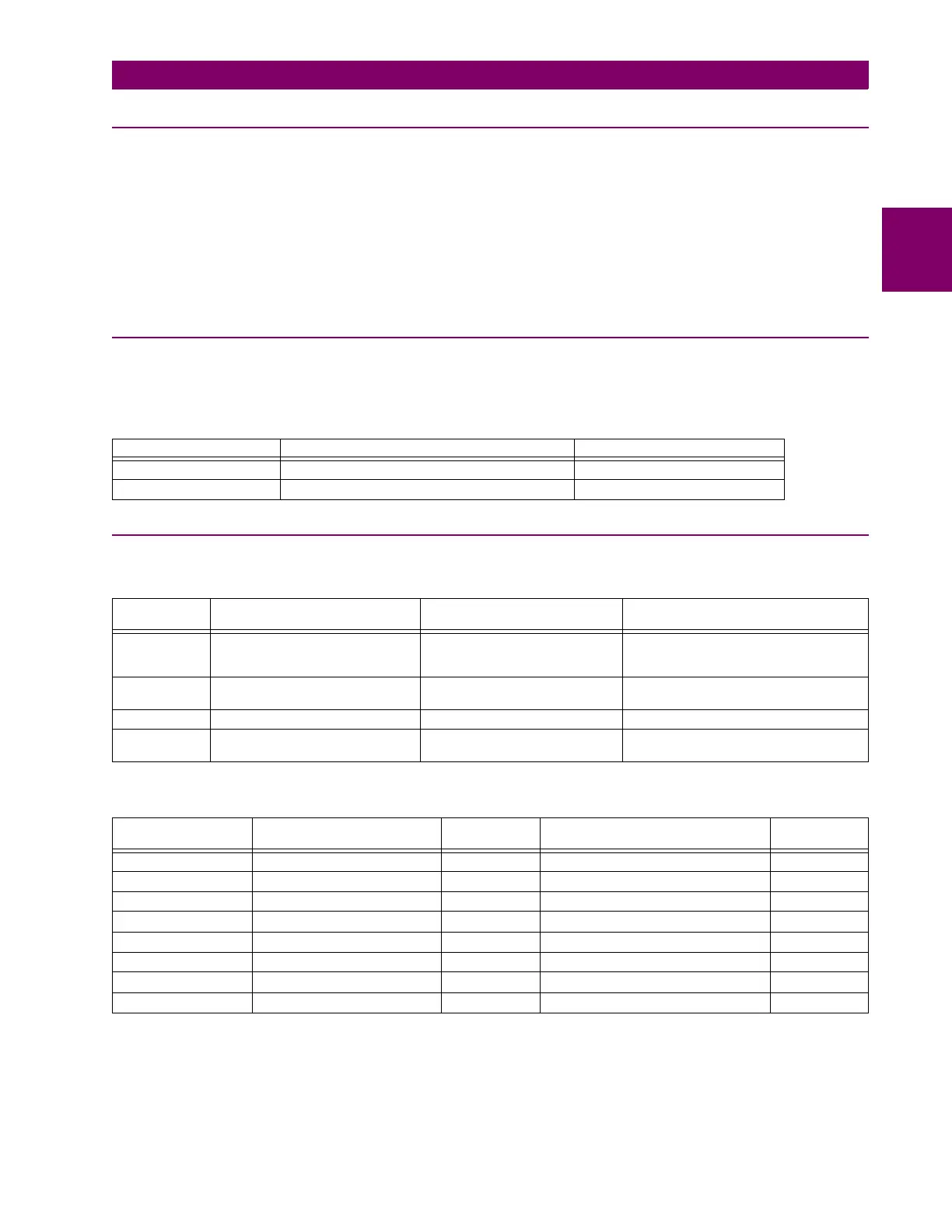
Both monitoring and control is possible using read and write functions mentioned above. The following table shows the
device register categories.
Table B–1: REQUIRED SETTINGS FOR MODBUS COMMUNICATIONS
SETTING MODBUS VALUE/MEANING FACTORY DEFAULT VALUE
UNIT ID
Modbus Address: valid only from 1 to 247. 0000
REMOTE BAUD RATE
Modbus Baud Rate: 1200, 2400, 4800, and 9600 9600
FUNCTION
CODE (DEC)
NAME PURPOSE REGISTER GROUPS
03/04 Read Holding (Setpoint) Registers;
Read Input Registers
Reading the setpoint/actual value
registers
Setpoint registers; control registers;
dynamic values, fixed values, faults,
events, and reports
05 Force Single Coil Activate single coil or control
trigger
Coil registers
06 Preset Single Register Writing one register Setpoint registers; control registers
16 Preset Multiple Registers Writing one or more registers Setpoint registers (limited set only: Date,
Time, Station ID and Line ID)
REGISTER TYPE CATEGORY START
ADDRESS
CONTENTS ACCESS
Input Registers Fixed Value Registers 0000 Fixed data reported by the device. Read Only
Input Registers Dynamic Value Registers 1000 Metering data and dynamic status data. Read Only
Input Registers Fault Registers 1500 Summary of fault data. Read Only
Report Registers Event Registers 2000 Summary of Event data. Read Only
Report Registers Fault Report Registers 20000 Report data ---
Report Registers Oscillography Report Registers. 20000 Report data. Read Only
Setpoint Registers Setting Registers 3000 Device settings. Read/Write
Coil Registers Coil Command Registers 500 Command coils used for activation. Write Only