3-10 ALPS Advanced Line Protection System
GE Power Management
3.3 PRINTED CIRCUIT BOARD MODULES 3 HARDWARE DESCRIPTION
3
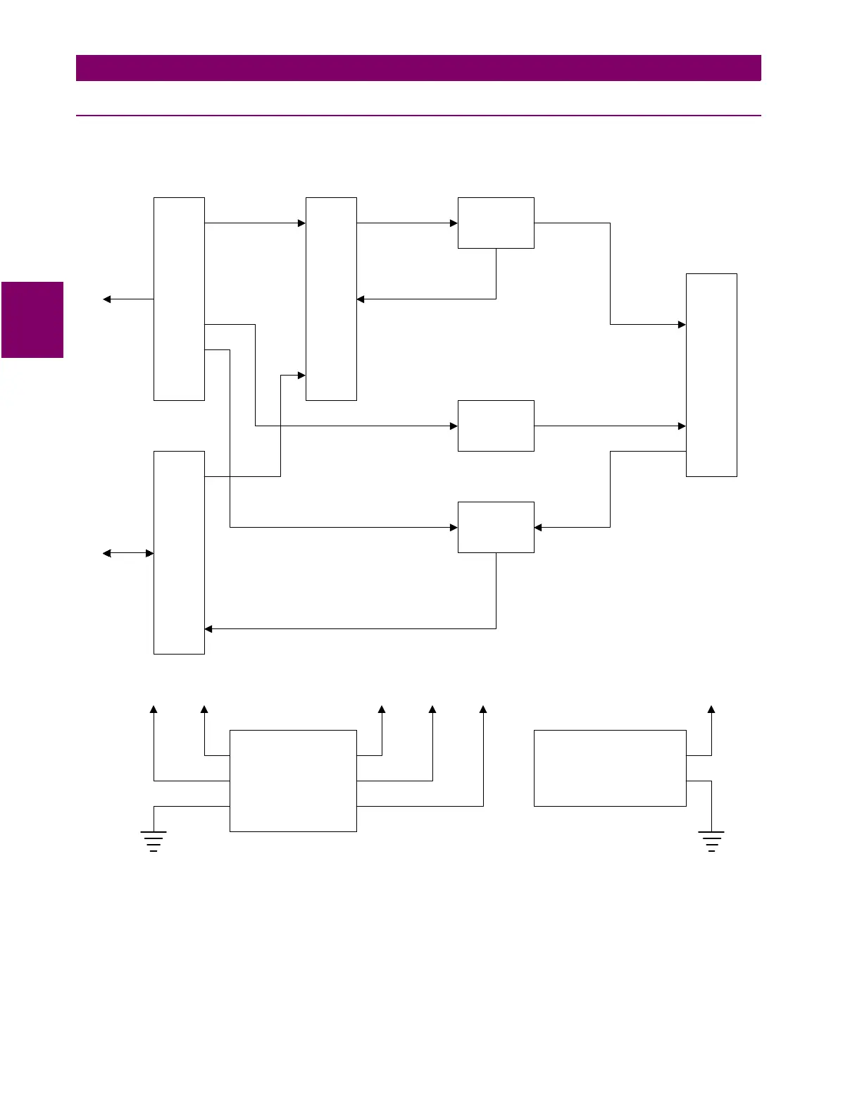
3.3.8 DIGITAL OUTPUT / POWER SUPPLY BOARD
The Digital Outputs, which are programmable are located on this board. The logic to select and write a digital output is
located on this board. The power supply circuitry is also contained on this board. See the block diagram below.
Figure 3–8: BLOCK DIAGRAM OF THE DIGITAL OUPUT / POWER SUPPLY
TRIP
RELAY
RELAY
LATCH
RELAY
LATCH
POWER SUPPLY
5 V 20 mA
CHANNEL INTERFACE
COMPARATOR
TRANSCEIVER DECODER
COMPARATOR
+5V+5V +12V ±12VANA+5VISO+12VISO
ADDRESS
DATA