GE Power Management
ALPS Advanced Line Protection System 13-9
13 XPRESSION BUILDER 13.3 CREATING XPRESSION BUILDER LOGIC
13
13.3 CREATING XPRESSION BUILDER LOGIC 13.3.1 DESCRIPTION
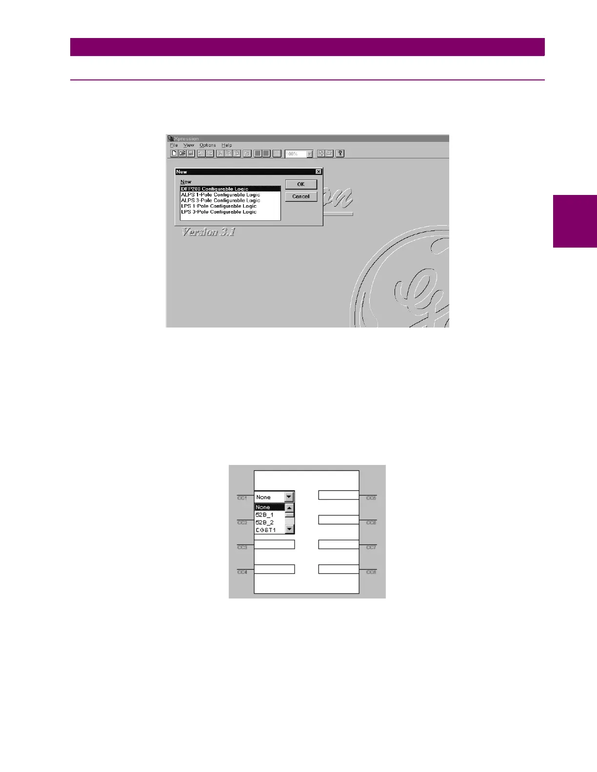
In the Xpression Builder program, Select File followed by New. A menu window for ALPS / LPS / DFP200 options will be
displayed as shown in Figure 13–6: CREATING A NEW FILE. For examination purposes, select ALPS 3-Pole Config-
urable Logic. A working screen will be displayed for an ALPS Three Phase Tripping unit.
Figure 13–6: CREATING A NEW FILE
The next step in the design of configurable logic is to determine the need for digital inputs. Typical inputs assigned to con-
tact converters are channel receivers and 52_b contacts. Other inputs can come from external contacts, other relay out-
puts, or the feedback of one of the ALPS outputs to an input. The list of available contact converter input assignments can
be found in Table 13–2: CONTACT CONVERTER INPUT FLAGS. In effect, this process does nothing more than associate
a given digital input with a name that Xpression Builder can use. Selection of the contact converter (CC) box, for example
CC1, with the left mouse button will activate a pull down menu from where flags can be assigned to the respective input as
shown in Figure 13–7: CONTACT CONVERTER INPUTS (CC). Double clicking on the CC box near the input bar with the
right mouse button will give the input an inverted sense and a NOT logical gate will appear on the input bar as shown in Fig-
ure 13–8: INVERTED CC INPUTS. A straight input will require a pickup voltage presence to be considered a high input
(logic 1). An inverted input will require a pickup voltage presence to be considered a low input (logic 0).
Figure 13–7: CONTACT CONVERTER INPUTS (CC)