C-4 ALPS Advanced Line Protection System
GE Power Management
C.2 DEVICE PROFILE APPENDIX C
C
C.2.2 IMPLEMENTATION TABLE
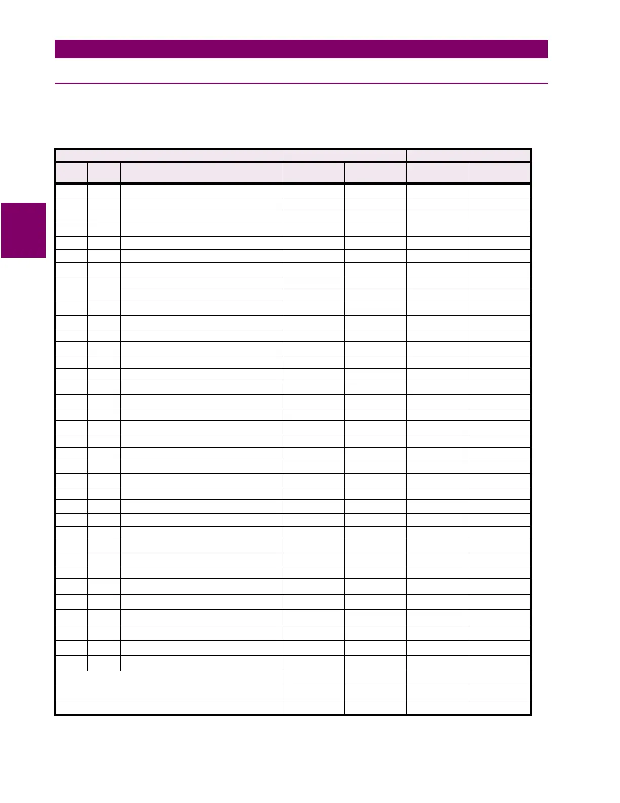
The implementation table gives a list of all objects recognized and returned by the ALPS device. Additional information
detailing a list of default variations returned for each object and lists of defined point numbers for each object is provided on
the following pages.
Table C–1: IMPLEMENTATION TABLE
OBJECT REQUEST RESPONSE
OBJ VAR DESCRIPTION
FUNC CODES
(DEC)
QUAL CODES
(HEX)
FUNC CODES
(DEC)
QUAL CODES
(HEX)
1 0 Binary Input – All Variations 1 06
1 1 Binary Input 1 00, 01, 06 129 00, 01
1 2 Binary Input With Status 1 00, 01, 06 129 00, 01
2 0 Binary Input Change – All Variations 1 06, 07, 08
2 1 Binary Input Change Without Time 1 06, 07, 08 129 17, 28
2 2 Binary Input Change With Time 1 06, 07, 08 129 17, 28
10 0 Binary Output – All Variations 1 06
10 2 Binary Output Status 1 00, 01, 06 129 00, 01
12 1 Control Relay Output Block 5, 6 17, 28 129 17, 28
20 0 Binary Counter – All Variations 1, 7, 8, 9, 10 06 129 00, 01
20 5 32-Bit Binary Counter without Flag 1, 7, 8, 9, 10 06 129 00, 01
20 6 16-Bit Binary Counter without Flag 1, 7, 8, 9, 10 06 129 00, 01
21 0 Frozen Counter – All Variations 1 06 129 00, 01
21 9 32-Bit Frozen Counter without Flag 1 06 129 00, 01
21 10 16-Bit Frozen Counter without Flag 1 06 129 00, 01
30 0 Analog Input – All Variations 1 06
30 1 32-Bit Analog Input with Flag 1 00, 01, 06 129 00, 01
30 2 16-Bit Analog Input with Flag 1 00, 01, 06 129 00, 01
30 3 32-Bit Analog Input without Flag 1 00, 01, 06 129 00, 01
30 4 16-Bit Analog Input without Flag 1 00, 01, 06 129 00, 01
32 0 Analog Change Event – All Variations 1 06, 07, 08
32 1 32-Bit Analog Change Event without Time 1 06, 07, 08 129 17, 28
32 2 16-Bit Analog Change Event without Time 1 06, 07, 08 129 17, 28
32 3 32-Bit Analog Change Event with Time 1 06, 07, 08 129 17, 28
32 4 16-Bit Analog Change Event with Time 1 06, 07, 08 129 17, 28
40 0 Analog Output Status – All Variations 1 06
40 1 32-Bit Analog Output Status 1 00, 01, 06 129 00, 01
40 2 16-Bit Analog Output Status 1 00, 01, 06 129 00, 01
41 1 32-Bit Analog Output Block 5, 6 17, 28 129 17, 28
41 2 16-Bit Analog Output Block 5, 6 17, 28 129 17, 28
50 1 Time And Date 1, 2
07
1
129 07
60 1
Class 0 Data
2
106
60 2
Class 1 Data
3
1 06, 07,. 08 129
60 3
Class 2 Data
3
1 06, 07, 08 129
60 4
Class 3 Data
3
1 06, 07, 08 129
80 1 Internal Indications 2
00
4
129
No Object (Cold Start Command) 13
No Object (Warm Start Command)
5
14
No Object (Delay Measurement Command)
6
23
1
,
2
,
3
,
4
,
5
,
6
See IMPLEMENTATION TABLE NOTES section on the following page