GE Power Management
ALPS Advanced Line Protection System 3-9
3 HARDWARE DESCRIPTION 3.3 PRINTED CIRCUIT BOARD MODULES
3
3.3.7 COMMUNICATIONS INTERFACE
The communications interface resides on plug-in modules with user selectable jumpers to configure the interface for the
communications application. The two communications types that can be chosen are RS232 and RS485. See the descrip-
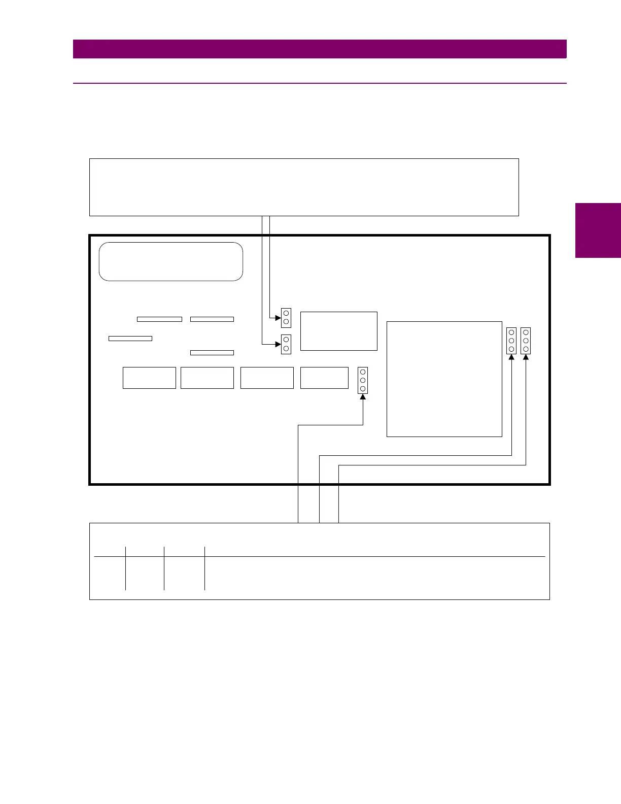
tion below for details. See Figure 3–7: BLOCK DIAGRAM OF THE COMMUNICATIONS MODULE below.
Figure 3–7: BLOCK DIAGRAM OF THE COMMUNICATIONS MODULE
EXTERNAL CONNECTOR AREA
EDGE CONNECTOR EDGE CONNECTOR
3
2
1
3
2
1
JP4 and JP5 select the RS485 type when RS485 commmunications is selected (2 wire/4 wire)
Both jumpers installed: 2-wire type RS485
Both jumpers uninstalled: 4-wire type RS485
(Uninstalled means the jumpers installed on one post -- the outside one -- to store the jumper. There will be no
electrical connection with jumpers in this position)
Jumpers JP1, JP2, and JP3 are used to determine the types of communications
JP1
JP2
JP3 TYPE OF COMMUNICATIONS
OPEN 2-3 OPEN RS232
2-3 OPEN 2-3 RS485
1-2 1-2 1-2 Programmable from keypad or communications (refer to Chapters 2 and 12)