GE Power Management
ALPS Advanced Line Protection System 8-27
8 LOCAL USER INTERFACE 8.4 REMOTE COMMUNICATION INTERFACE
8
8.4.5 NULL-MODEM CONNECTIONS
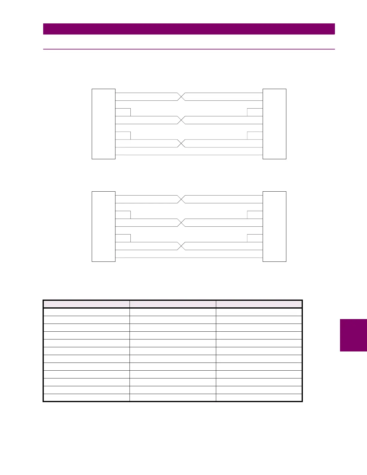
A PC can be connected directly to the relay without a modem through a null-modem cable. The required pin-to-pin connec-
tions for the PC null-modem cable are shown below in Figure 8–4: 25-PIN NULL MODEM CABLE. The pin-to-pin connec-
tions for a null-modem cable to the 9-pin connector on the KEYPAD/DISPLAY INTERFACE are shown below in Figure 8–5:
NULL MODEM CABLE FOR PORT PL1. The null modem cable should be no more than 50 feet long.
Figure 8–4: 25-PIN NULL MODEM CABLE
Figure 8–5: NULL MODEM CABLE FOR PORT PL1
Table 8–6: MODEM COMMANDS FOR COMMUNICATION BETWEEN RELAY AND PC
FUNCTION ALPS MODEM (REMOTE) PC MODEM (LOCAL)
DTR Status Follow DTR (&D3) Follow DTR (&D3)
Result Code Format Numeric (V0) Numeric (V0)
Result Code Display Disable (Q1) Disable (Q1)
Command State Echo Disable (E0) Disable (E0)
Auto-Answer Enable (S0=1) Disable (S0=0)
Carrier Detect Follow CD (&C1) Follow CD (&C1)
Jack Type RJ-11, etc. (&J0) RJ-11, etc. (&J0)
Command Recognition Disable (Dumb) Enable (Smart)
Comm. Std. (@1200 bps) Bell 212A (B1) Bell 212A (B1)
Response to DTR Ignore DTR (&D0) Ignore DTR (&D0)
Fall Back to 4800Bd AT#F1
Pulse Dial Ratio 39%Mk/61%Bk (&P0) 39%Mk/61%Bk (&P0)
2
7
20
22
6
8
5
4
3
7
20
22
6
8
5
4
3
2
TO RELAY
PL-2 & 3
TO PC
REMOTE COMMUNICATIONS PC DIRECTLY
NULL MODEM CABLE
GND
DTR
RI
DSR
DCD
CTS
RTS
RD
TD
GND
DTR
RI
DSR
DCD
CTS
RTS
RD
TD
2
5
1
8
7
4
9
6
3
5
1
8
7
4
9
6
3
2
TO RELAY
PL-1
TO PC
REMOTE COMMUNICATIONS FROM PL-1 MODULE
NULL MODEM CABLE
GND
DCD
CTS
RTS
DTR
RI
DSR
RD
TD
GND
DCD
CTS
RTS
DTR
RI
DSR
RD
TD