GE Power Management
ALPS Advanced Line Protection System 1-13
1 PRODUCT DESCRIPTION 1.4 AUXILIARY PROTECTION FUNCTIONS
1
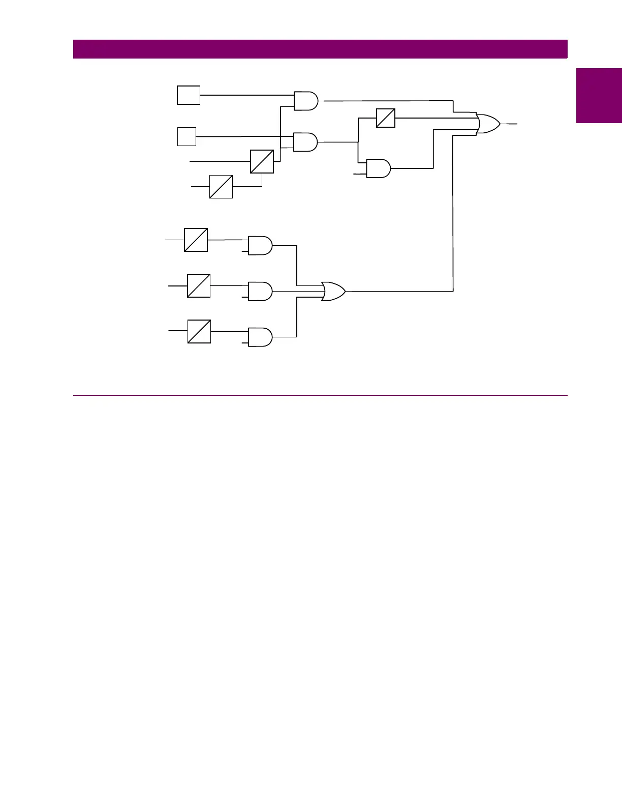
Figure 1–5: LINE PICKUP LOGIC DIAGRAM (SINGLE PHASE TRIPPING)
1.4.3 REMOTE-OPEN DETECTOR
The Remote-Open Detector (ROD) function issues a trip signal when the remote breaker opens during an unbalanced
internal fault. This function detects that the remote breaker has opened by recognizing charging current on one or more
phases following opening of the remote breaker. As shown in the functional logic diagram of Figure 1–6: REMOTE-OPEN
DETECTOR LOGIC (ROD), the ROD output trips via OR2, AND1, OR2, AND2, OR3, and AND4. The Remote-Open Detec-
tor will not operate when a balanced three-phase fault is present.
ROD speeds up tripping at the end of the line that otherwise would be the slowest to respond in a sequential-tripping condi-
tion. In a Step Distance scheme, ROD tripping is beneficial for any unbalanced internal fault not detected by Zone 1. In a
Blocking scheme, ROD tripping is beneficial where system conditions are such that the fault current redistribution following
breaker opening at one end is normally required before the other end(s) operates. The ROD function should not be consid-
ered as a replacement or substitute for pilot schemes.
Figure 1–6: REMOTE-OPEN DETECTOR LOGIC (ROD) is a functional logic diagram of the ROD function. The sequence
of events that results in an ROD output is as follows:
1. No charging current is detected prior to the fault – logic 0 output from AND2.
2. A fault is detected – logic 1 output from OR3.
3. The remote breaker opens – logic 1 output from AND3.
4. The fault is still present, so the two inputs to AND4 persist for the time-delay setting of timer TL20.
If charging current is initially detected but the fault detector (FD) is not picked up, indicating no fault on the power system,
then OR1 and AND1 produce outputs. AND2 produces an output and seals-in on the output of OR1 via OR2. AND3 is now
blocked from producing an output as long as charging current is detected, regardless of whether FD is picked up or not. If a
subsequent fault occurs and the remote breaker opens, ROD is prevented from producing an output.
TIMER
BYPASS
45
5
150
90
40
0
MT
MTG
I1
ALL PHASE VOLTAGES
HIGH
ALL PHASES OPEN
I1 CURRENT
DETECTOR
OVERREACHING PHASE OR
GROUND DISTANCE
LINE PICKUP
TRIP
401
402
403
TL403
TL401
TL402
FAST
RESET
150
90
150
90
150
90
MTG A
MTG B
MTG C
PHASE A
OPEN
PHASE B
OPEN
PHASE C
OPEN
404
405
406
402
TL404
TL405
TL406
401