4-8 ALPS Advanced Line Protection System
GE Power Management
4.2 GENERAL RELAY TESTS 4 ACCEPTANCE/PERIODIC TESTS
4
4.2.3 T2 – DIGITAL OUTPUT TEST
This test checks all outputs of the relay. It is a convenient way to determine proper system connections and verify the oper-
ation of all relay contacts, without having to apply currents and voltages to simulate faults. Protection can be enabled or dis-
abled, as deemed necessary.
If this test is run remotely through ALPS-Link, then switch RM BRKR must be in the down position to allow
the outputs to operate. Refer to Section 8.4.1: HARDWARE SWITCHES on page 8–24 for details on chang-
ing the switch position. Note that the relay is shipped from the factory with the switch in the down position
allowing the outputs to operate.
1. Connect the relay as shown in Figure 4–1: DIGITAL OUTPUTS TEST CONNECTIONS on page 4–9.
2. Press the [ACT] key and enter the control level password.
3. Use the arrow key to select 8. Digital Output Test
4. Press the [ENT] key. Before a contact is allowed to be tested, the display prompts DISABLE PROTECT?
5. Press the [1/Y] key followed by the [ENT] key to turn protection off. Protection remains off until the test mode is ended
(if desired, protection can be left enabled during the test).
6. Select the output to test by using the arrow keys to scroll to the desired output, such as T1, and press the [ENT] key.
When the digital output is chosen, the selected relay output closes. Verify that the output under test has closed, using
an ohmmeter or other suitable device.
7. After the output is tested, scroll to the next output to test, then press the [ENT] key. This output closes and the previ-
ously selected output opens. Continue in this fashion until all outputs are tested.
8. End the test mode by scrolling to the END TEST MODE selection, then press the [ENT] key. Alternatively, press [END]
followed by the [ENT] key to end the test and re-enable protection.
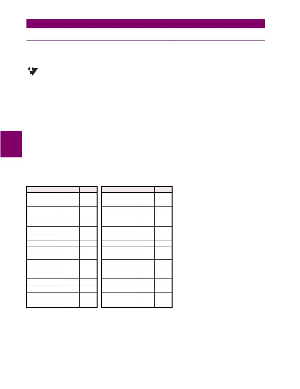
Table 4–2: DIGITAL OUTPUTS TEST CONNECTIONS
OUPTUT X Y OUTPUT X Y
T1 A3 A19
A12
†
B4 B20
T2 A4 A20 KT1 (no) B5 B21
T3 A5 A21 KT1 (nc) B5 B22
T4 A6 A22 KT2 (no) B5 B21
T5
†
A7 A23 KT2 (nc) B23 B7
T6
†
A8 A24 KT3 (no) B8 B24
A1 A9 A25 KT3 (nc) B8 B25
A2 A10 A26 KT4 (no) B26 B9
A3 A11 A27 KT4 (nc) B26 B10
A4 A12 A28 C1A (no) B11 B27
A5 A13 A29 C1B (nc) B11 B28
A6 A14 A30 C2A (no) B29 B12
A7 A15 A31 C2B (nc) B29 B13
A8 A16 A32 CA (nc) B14 B30
A9
†
B1 B17 CA (no) B14 B31
A10
†
B2 B18 PWR (nc) B32 B15
A11
†
B3 B19 PWR (no) B32 B16
Tx
- TRIPPING contacts (programmable)
Ax
- Alarm contacts (programmable)
KTx
- Key Transmitter contacts (programmable)
Cxy
- C Form contacts with one NO/NC contact pair (programmable)
CA
- Critical Alarm
PWR
- Power Supply Alarm
†
These digital outputs apply to the Single Phase Tripping model only.
NOTE