GE Power Management
ALPS Advanced Line Protection System 1-5
1 PRODUCT DESCRIPTION 1.2 INTRODUCTION
1
1.2.4 GROUND DISTANCE QUADRILATERAL CHARACTERISTICS
The ALPS relay has been modified to include the option to use either quadrilateral characteristics or variable Mho charac-
teristics for all zones of ground distance protection. The model numbers affected by this modification are: ALPSD-
B
XXXXXXXXX
(where
X
may be any valid character) with firmware version V0005.00AA00 or higher. A new version of
ALPS-Link may be required to access the new settings via remote communications (ALPS-Link must be version 3.5 or
higher). If required, the updated version of ALPS-Link may be downloaded from the GE power Management website at
www.GEindustrial.com/pm
.
Many protective relay engineers prefer to use a quadrilateral (polygonal) characteristic for ground distance functions to pro-
vide more fault resistance coverage than the circular mho characteristic. A typical quadrilateral characteristic is shown in
Figure 1–1: GROUND DISTANCE QUADRILATERAL CHARACTERISTIC. The characteristic is comprised of four straight
lines; the trip zone is the inside area bounded by all four characteristics. The upper boundary, the reactance characteristic,
may also be used with a variable mho function. The variable mho provides both directional supervision for reverse faults.
and resistive limits to prevent operation on load.
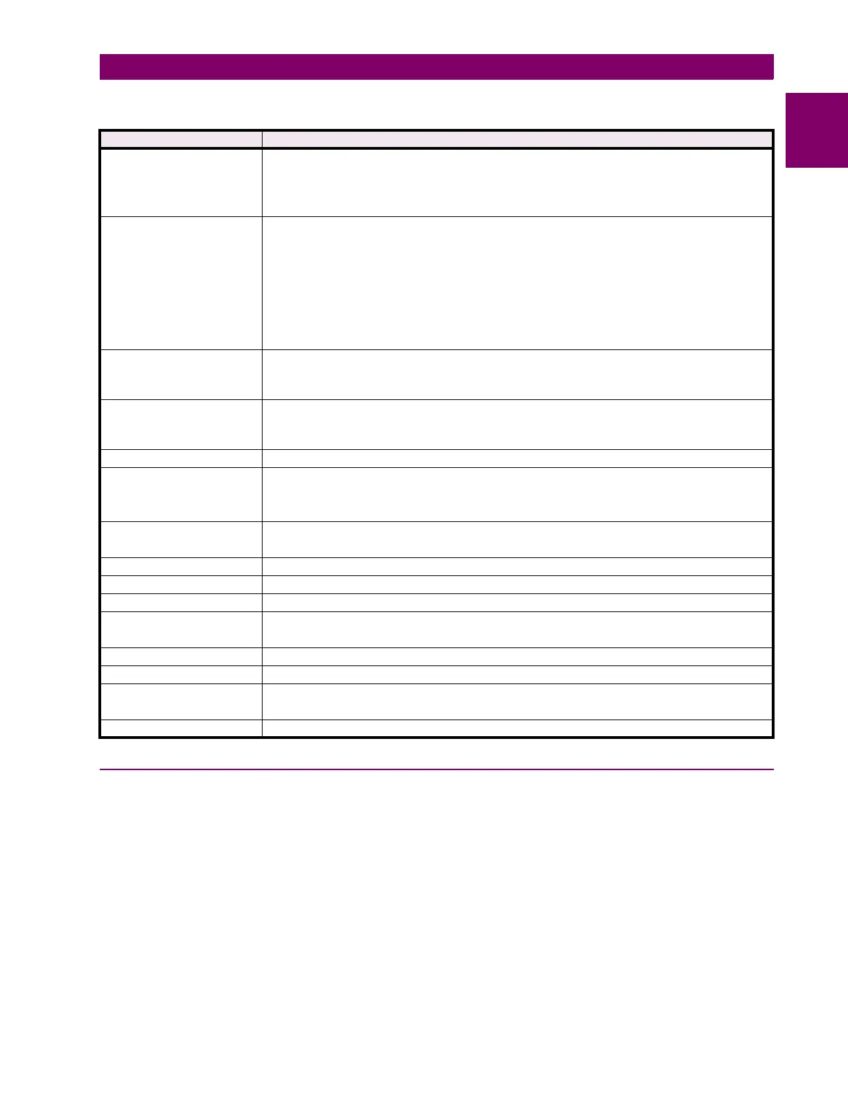
Table 1–2: ALPS MEASUREMENT FUNCTIONS
ZONE OR TYPE FUNCTIONS
Zone 1 • 3 Variable-Mho phase-distance functions
• 3 Variable-Mho ground-distance functions
• 3 Reactance ground-distance functions with “adaptive reach” Mho supervision
or
3 Quadrilateral ground-distance functions (Revision B relays only).
Zone 2 (Pilot Zone) • 3 Variable-Mho phase distance functions
3 Variable Mho ground-distance functions
and/or
Ground directional-overcurrent functions consisting of:
IPT: Ground Trip overcurrent
NT: Negative Sequence Directional Trip
IPB: Ground Block overcurrent
NB: Negative Sequence directional block
or
3 Quadrilateral ground-distance functions (Revision B relays only)
Zone 3 • 3 Variable-Mho phase-distance functions
• 3 Variable-Mho ground-distance functions,
or
3 Quadrilateral ground-distance functions (Revision B relays only)
Zone 4 • 3 Reversible variable-Mho phase-distance functions
• 3 Reversible variable-Mho ground-distance functions,
or
3 Quadrilateral ground-distance functions (Revision B relays only)
Out of Step Blocking (OSB) • 3 Variable-Mho phase-distance functions
Overcurrent Backup • 50: Phase-overcurrent direct trip (directional or nondirectional
• 50G: Ground-overcurrent direct trip (directional or nondirectional)
• 51G: Ground time-overcurrent direct trip (directional or nondirectional)
Overcurrent Supervision • IT: Trip-supervision overcurrent
• IB: Block-supervision overcurrent
Fault Detector • FD
Line-Pickup Overcurrent • I1
Remote-Open Detectors • ROD
Line-Overload Detectors • Level 1 Overcurrent
• Level 2 Overcurrent
Phase Undervoltage • Three fixed pickup phase undervoltage detectors
Phase Over / Undervoltage • Three adjustable over or under voltage detectors with time delay
Positive-Sequence Voltage
Detectors
•V1,
• V1 compensated
Out of Step Tripping (OST) • 3 Variable-Mho positive sequence-distance functions