GE Power Management
ALPS Advanced Line Protection System 8-11
8 LOCAL USER INTERFACE 8.1 INTRODUCTION
8
If YES is chosen, the outputs are enabled, the status LED may turn GREEN (if disabling outputs or relay test was the cause
to turn it RED), and the ACT command menu is displayed. If NO is chosen, the outputs remain disabled, the status LED
stays RED and the ACT command menu is displayed. If any other key is pressed, an error message is generated and
[CLR] key must be pressed to clear the message.
The available ALPS tests and their corresponding numbers are:
8.1.17 CHANNEL TEST
This command is used to allow the user to key (turn on) the local transmitter when a channel scheme (POTT1, POTT2,
PUTT, BLOCKING, or HYBRIDP) is used. Protection must be enabled to perform a channel test. If protection is disabled
when channel test is selected, the relay will prompt the user to enable protection.
If the [3/N] (NO) key is pressed, CANCELED is displayed and the test canceled. If the [1/Y] (YES) key is pressed, the relay
checks the outputs. If they are enabled, the test item is displayed. If the outputs are disabled, the user is prompted to
enable them. If the user responds with [3/N] (NO), CANCELED is displayed and the test is canceled. If the user responds
[1/Y] (YES), the outputs are enabled and the test item is displayed.
If 2. Channel test is selected, the privilege level must be CONTROL or MASTER and communications must not be per-
forming an action. If either check fails, an error message is displayed and the test is not performed. The error message
must be cleared by pressing the [CLR] key. When the checks pass and the test is started, the word ON will be displayed to
the right of the item.
When the user selects 1. End Chnl Test, the test is terminated and the user is returned to the Actions menu.
1: End Test Mode 17: ANY Z4 GND 33: ANY Z4 PHASE
2: ZONE 1 AG 18: ZONE 1 AB 34: IT DETECTOR
3: ZONE 1 BG 19: ZONE 1 BC 35: IB DETECTOR
4: ZONE 1 CG 20: ZONE 1 CA 36: GRD DIR TRIP
5: ZONE 2 AG 21: ZONE 2 AB 37: GRD DIR BLOCK
6: ZONE 2 BG 22: ZONE 2 BC 38: FAULT DETECTOR
7: ZONE 2 CG 23: ZONE 2 CA 39: REM OP DETCT
8: ZONE 3 AG 24: ZONE 3 AB 40: OUT OF STEP BLK
9: ZONE 3 BG 25: ZONE 3 BC 41: V1 DETECTOR
10: ZONE 3 CG 26: ZONE 3 CA 42: LINE OVERLOAD
11: ZONE 4 AG 27: ZONE 4 AB 43: INST PHS OVRC
12: ZONE 4 BG 28: ZONE 4 BC 44: INST GND OVRC
13: ZONE 4 CG 29: ZONE 4 CA 45: LINE PICKUP
14: ANY Z1 GND 30: ANY Z1 PHASE 46: OVER VOLTAGE
15: ANY Z2 GND 31: ANY Z2 PHASE 47: UNDER VOLTAGE
16: ANY Z3 GND 32: ANY Z3 PHASE 48:OUT OF STEP TRIP
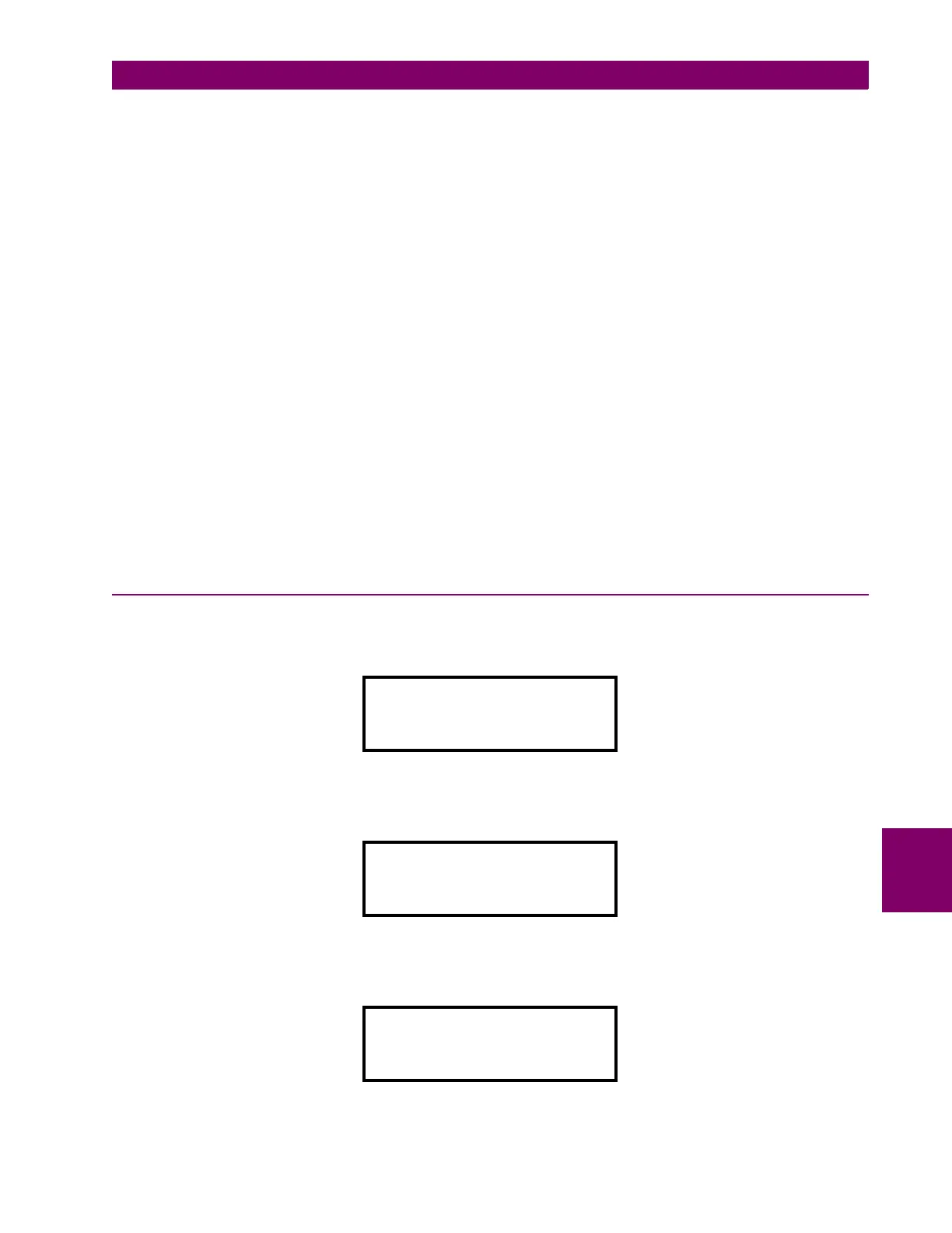
CHANNEL TEST
Enable Protection?
CHANNEL TEST
1.End Chnl Test
2.Channel Test
CHANNEL TEST
1.End Chnl Test
2.Channel Test ON