GE Power Management
ALPS Advanced Line Protection System 2-65
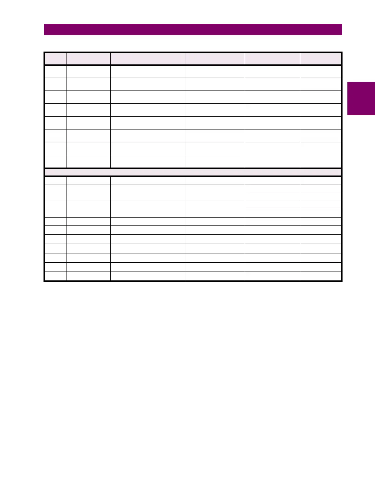
2 CALCULATION OF SETTINGS 2.5 REFERENCE TABLES
2
403 MAX_IXT Maximum Breaker Duty for a
Breaker
0 to 9999999 A
x
sec.
100 0
404 IXTPHASEA Accumulated Breaker Duty,
Phase A
0 to 9999999 A
x
sec.
100 0
405 IXTPHASEB Accumulated Breaker Duty,
Phase B
0 to 9999999 A
x
sec.
100 0
406 IXTPHASEC Accumulated Breaker Duty,
Phase C
0 to 9999999 A
x
sec.
100 0
407
‡
NUM_OP Present Number of Breaker
Operations
0 to 9999 1 0
407
†
NUM_OP_A Present Number of Breaker
Operations for Phase A
0 to 9999 1 0
408
†
NUM_OP_B Present Number of Breaker
Operations for Phase B
0 to 9999 1 0
409
†
NUM_OP_C Present Number of Breaker
Operations for Phase C
0 to 9999 1 0
INPUTS
501 CC1 Contact Converter 1 0 to 32
*
112
502 CC2 Contact Converter 2 0 to 32
*
113
503 CC3 Contact Converter 3 0 to 32
*
110
504 CC4 Contact Converter 4 0 to 32
*
111
505 CC5 Contact Converter 5 0 to 32
*
1
7
†
506 CC6 Contact Converter 6 0 to 32
*
1
507 CC7 Contact Converter 7 0 to 32
*
1
1
†
508 CC8 Contact Converter 8 0 to 32
*
2
†
, 4
‡
509
CC9
†
Contact Converter 9 0 to 32
*
1
3
†
510
CC10
†
Contact Converter 10 0 to 32
*
1
4
†
511
CC11
†
Contact Converter 11 0 to 32
*
1
5
†
512
CC12
†
Contact Converter 12 0 to 32
*
1
6
†
Table 2–12: GENERAL SETTINGS GUIDE (Sheet 2 of 2)
NO. MNEMONIC DESCRIPTION RANGE
(5A & 1A)
STEP DEFAULT
† Applicable to the Sin
le Phase Trippin
model only.
‡ Applicable to the Three Phase Trippin
model only.
*
Contact converter output normally appears as a Lo
ic 1 with normally open contact connected; to invert output to Lo
ic 0, add 1000 to
the number.