GE Power Management
ALPS Advanced Line Protection System 7-1
7 SPECIFICATIONS 7.1 ALPS SPECIFICATIONS
7
7 SPECIFICATIONS 7.1 ALPS SPECIFICATIONS 7.1.1 DESCRIPTION
ELECTRICAL RATINGS
Rated Frequency: 50 to 60 Hz
Rated Volta
e (ph-ph): 100 to 120 V AC
Rated Current
I
n
: 1 A or 5 A
DC Control Volta
e, operatin
ran
e:
48 V DC 38.5 to 60 V DC
110/125 V DC 88 to 150 V DC
220/250 V DC 176 to 300 V DC
Maximum Permissible AC volta
e:
Continuous 138 V AC (ph-n)
1 minute 208 V AC (ph-n)
Maximum Permissible current:
Continuous 3 x
I
n
3 seconds 50 x
I
n
1 second 100 x
I
n
Sample Rate: 64 per cycle
Hi-Pot (DC Test): ANSI C37.90; IEC 255-5
Sur
e Withstand Capability: ANSI C37.90.1; IEC 255-22-1
Impulse Volta
e Withstand Fast Transient:
5 kV peak, 1.2/50 ms, 0.5 J
ANSI C37.90.1
IEC255-4
Radio Frequency Interference Withstand:
ANSI C37.90.1;
IEC 255-22-1
Electrostatic Dischar
e: IEC255-22-2
Humidity: 95% without condensation
Ambient Temperature Ran
e
Stora
e: –30°C to 75°C
Operation: –20°C to 65°C
BURDEN RATINGS
Current Circuit:
I
n
= 1 A: 0.12 Ω @ 30°
I
n
= 5 A: 0.022 Ω @ 5°
Volta
e Circuit: 0.15 VA @ 60 Hz
0.20 VA @ 50 Hz
DC Battery:
(contact converters):2.5 mA at rated DC input
(power supply): < 20 W
Trip Circuit Motor: 150 mA for current-flow sensor
CONTACT RATINGS
Fault Location I/V: 0 to 1 mA, 10V load or 0 to 5 V output
(4 V = full scale; 5 V = error)
Trip Outputs (T1 to T4/T6):
Continuous Ratin
:5 A
Make and Carry: 30 A (per ANSI C 37.90)
Interruptin
: 25 VA
Pickup: < 4 ms
SCR Outputs: same as Trip Outputs
Auxiliary Outputs (A1 to A8/A12, C1, C2):
Continuous Ratin
:5A
Make and Carry: 30 A (per ANSI C 37.90)
Interruptin
: 25 VA
Pickup: < 8 ms
Hi
h Speed (KT1 to KT4):
Continuous Ratin
:0.5A
Maximum Volta
e: 280 V DC
Pickup: < 0.5 ms
Contact Converter Inputs:38.5 to 300 V DC
PROTECTION SCHEME SELECTION
Protection Schemes: Step Distance
POTT1 & POTT2
PUTT
Blockin
Hybrid
Phase-Identified Channel
Pro
rammable Lo
ic
Directional Control: Forward or Reverse
Time Synchronization: by demodulated IRIG-B si
nal (5 V DC)
Out-of-Step Blockin
Reach: The reach of MOB is that of the zone it is
coordinated with: Zone 2, Zone 3, or
Zone 4
Characteristic An
le: 30° to 130°
REACH SETTINGS
M1 (Zone 1 Phase Reach), M1G (Zone 1 Ground Reach)
Ran
e:
I
n
= 1 A: 0.05 to 250 Ω
I
n
= 5 A: 0.01 to 50 Ω
Resolution:
I
n
= 1A: 0.01 Ω
I
n
= 5 A: 0.01 Ω
MT (Zone 2 Phase Reach), MTG (Zone 2 Ground Reach)
Ran
e:
I
n
= 1 A: 0.05 to 250 Ω
I
n
= 5 A: 0.01 to 50 Ω
Resolution:
I
n
= 1A: 0.01 Ω
I
n
= 5 A: 0.01 Ω
M3 (Zone 3 Phase Reach), M3G (Zone 3 Ground Reach)
Ran
e:
I
n
= 1 A: 0.05 to 250 Ω
I
n
= 5 A: 0.01 to 50 Ω
Resolution:
I
n
= 1A: 0.01 Ω
I
n
= 5 A: 0.01 Ω
M4 (Zone 4 Phase Reach), M4G (Zone 4 Ground Reach)
Ran
e:
I
n
= 1 A: 0.05 to 250 Ω
I
n
= 5 A: 0.01 to 50 Ω
Resolution:
I
n
= 1A: 0.01 Ω
I
n
= 5 A: 0.01 Ω
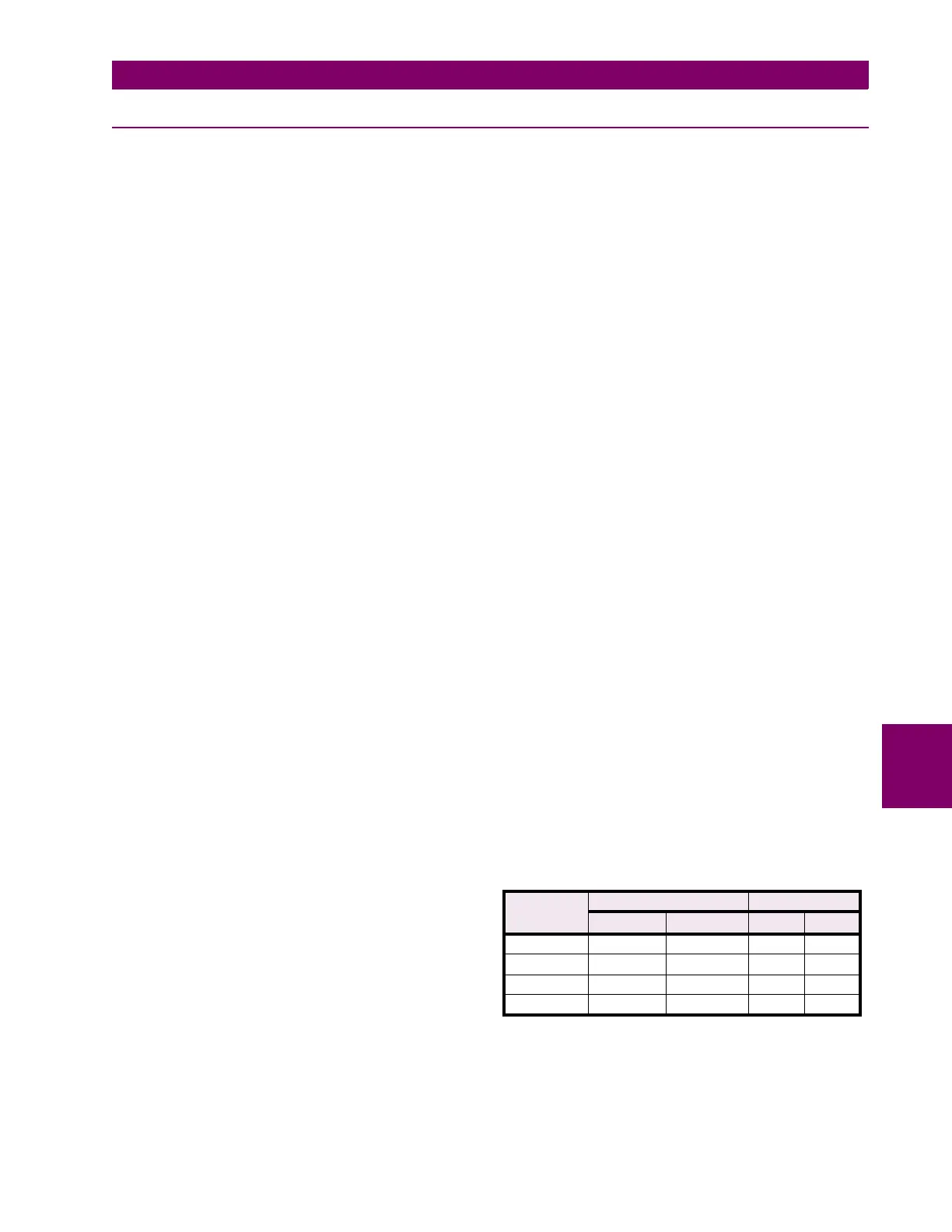
CURRENT SUPERVISION FUNCTION
FUNCTION RANGE
Α
RESOLUTION
Α
I
n
= 5 A
I
n
= 1 A
I
n
= 5 A
I
n
= 1A
IPT 0.50 to 5.00 0.10 to 1.00 0.01 0.01
IPB 0.25 to 3.75 0.05 to 0.75 0.01 0.01
IT 0.20 to 4.00 0.20 to 4.00 0.01 0.01
IB 0.20 to 4.00 0.20 to 4.00 0.01 0.01