GE Power Management
ALPS Advanced Line Protection System 13-3
13 XPRESSION BUILDER 13.1 INTRODUCTION
13
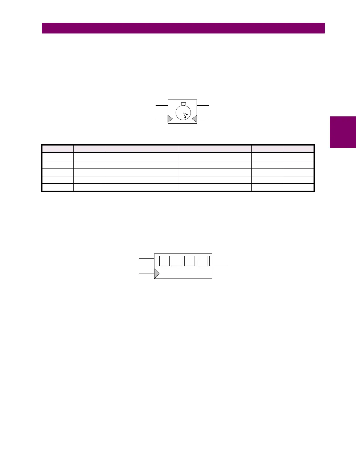
The second type of timer is basically a pickup delay timer with a reset input/output feature. As shown in Figure 13–4:
PICKUP DELAY TIMER, there are two inputs, two outputs, and a user selected pickup delay (in milliseconds). In its “initial”
state with no inputs applied, both R and S are low (binary 0), the timer outputs RO and SO are both low (binary 0). The
timer starts counting when the S input is high (binary 1). When the count becomes equal to the set time delay (1000 ms for
our example), the SO output is set high (binary 1) and the RO output is set low (binary 0). If the R input becomes high
(binary 1) while the timer IS NOT counting, then both outputs RO and SO are set low (binary 0) which returns the timer to
its “initial state”. See Table 13–1: PICKUP DELAY TIMER TRUTH TABLE for a summary of the pickup delay timer function.
Figure 13–4: PICKUP DELAY TIMER
d) COUNTERS
The counter has two input line, one output line, and a user selected count threshold (in milliseconds) as shown in Figure
13–5: COUNTER. A transition from low (binary 0) to high (binary 1) on the S input line increments the counter by a value of
one. The O output line is high (binary 1) when the accumulated count is equal to or greater than the count threshold. If the
O output line is low (binary 0), then the accumulated count is less than the set value. A transition from low (binary 0) to high
(binary 1) on the R input line resets the counter to zero.
Figure 13–5: COUNTER
Table 13–1: PICKUP DELAY TIMER TRUTH TABLE
S R PREVIOUS TIMER STATE CURRENT TIMER STATE RO SO
L L NOT TIMING NOT TIMING RO
n-1
L
↑
L NOT TIMING TIMING DOWN L L
X L TIMING DOWN TIMER EXPIRED L H
X H TIMING DOWN TIMER RESET H L
X
↑
NOT TIMING NOT TIMING L L
1000
R
SSO
RO
0000
S
R
O
5