GE Power Management
ALPS Advanced Line Protection System 1-31
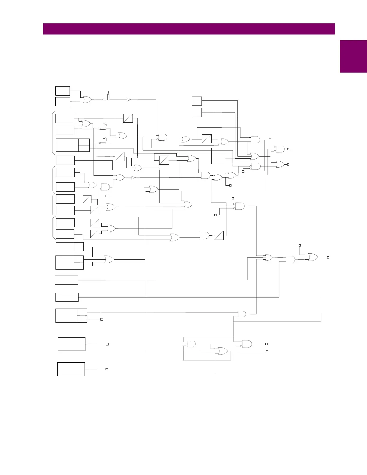
1 PRODUCT DESCRIPTION 1.8 PROTECTION SCHEMES
1
In a typical application with ON-OFF carrier sets, only one receiver is used at each terminal of the line, regardless of the
number of line terminals. The contact converter (RCVR 1 in the logic diagram) converts the receiver output into a blocking
signal usable by the ALPS. Some blocking schemes use frequency-shift tone channels, such as the GE type NS40A. For a
three-terminal application employing FSK tones, each terminal has two receivers and an additional contact converter must
be assigned. In the default settings, CC2 is used.
Figure 1–15: BLOCKING SCHEME LOGIC DIAGRAM
External contacts may be used to supervise the relay-channel interface. The EXTERNAL STOP CARRIER signal is
assigned to CC3 in the default settings. EXTERNAL STOP CARRIER turns the local transmitter OFF. This feature is typi-
cally used when the remote breaker must trip to clear a fault following a breaker failure. An external contact closure, indicat-
ing a breaker failure, produces an output from CC3 that turns the transmitter OFF, permitting the remote end to trip.
FAULT
DETECTOR
LINE PICKUP
(CANCL)
(RI)
3
4
F=1-50
TL1
F
50
25
X
B
0
3
407
3
8
301
508
302
209
22
213
208
CARRIER
START
CARRIER
STOP
OSB
(Zone 2)
TL24
2
[2 RCVRS]
[1 RCVR]
21
CC
(RCVR1)
CC
(RCVR2)
TL2G
B
0
REF
REF
B = 0.2- 3.0 SEC
CC
(STCR)
PHASE
DISTANCE
GROUND
DISTANCE
GROUND
DIRECTIONAL
OVER-
CURRENT
TRIP
BLOCK
REMOTE
OPEN
PHASE
DISTANCE
GROUND
DISTANCE
110
GROUND
BACKUP
OVER-
CURRENT
SUPERVISION
PHASE
DISTANCE
GROUND
DISTANCE
PHASE
DISTANCE
GROUND
DISTANCE
PHASE
BACKUP
50P
P
X
TL25
X=30-300
OSBALL
FFB
Setting 714
C
0
C
0
D
0
D
0
TL4G
TL4P
TL3G
TL3P
13
503
20
28
12
BLOCK ZONE 1
Setting 110
1
103
2
25
11
C=0.4-6sec
D=0.4-6sec
(Zone 4)
(Zone 3)
TIME DELAYED TRIP
REVERSIBLE
ZONE 4
ZONE 3
ZONE 1
OVERREACHING ZONE /
ZONE 2
13
Setting
1202
EXTERNAL
CARRIER STOP
EXTERNAL
BLOCK PILOT
TRIPPING
(KEY1)
(KEY2)
Setting
205
BlockScheme.vsd
OUT OF STEP
BLOCKING
LOGIC
OSB
Settings
1601 - 1607
(CNFTRP)
CONFIGURABLE
TRIP BUS
8
RECLOSE CANCEL
RECLOSE INITIATE
BLOCK RELCLOSING
Settings 801-810
9
(TRIP)
TRIP
BUS
44
7
7
6
303
103
BLOCK ZONE 1
Setting 110
Supervise Zone 4
FFB
Setting 714
PT FUSE
FAILURE
DETECTION
LOGIC
FFB
Setting 714
BLOCKS SELECTED PHASE AND
GROUND ZONE FUNCTIONS
DURING OUT OF STEP
CONDITION
X=30-300
T2LP
CC
(STCR)
51G
50G
IT
IB
9