3-38 L90 LINE CURRENT DIFFERENTIAL SYSTEM – INSTRUCTION MANUAL
PILOT CHANNEL COMMUNICATIONS CHAPTER 3: INSTALLATION
3
Figure 3-37: Switches
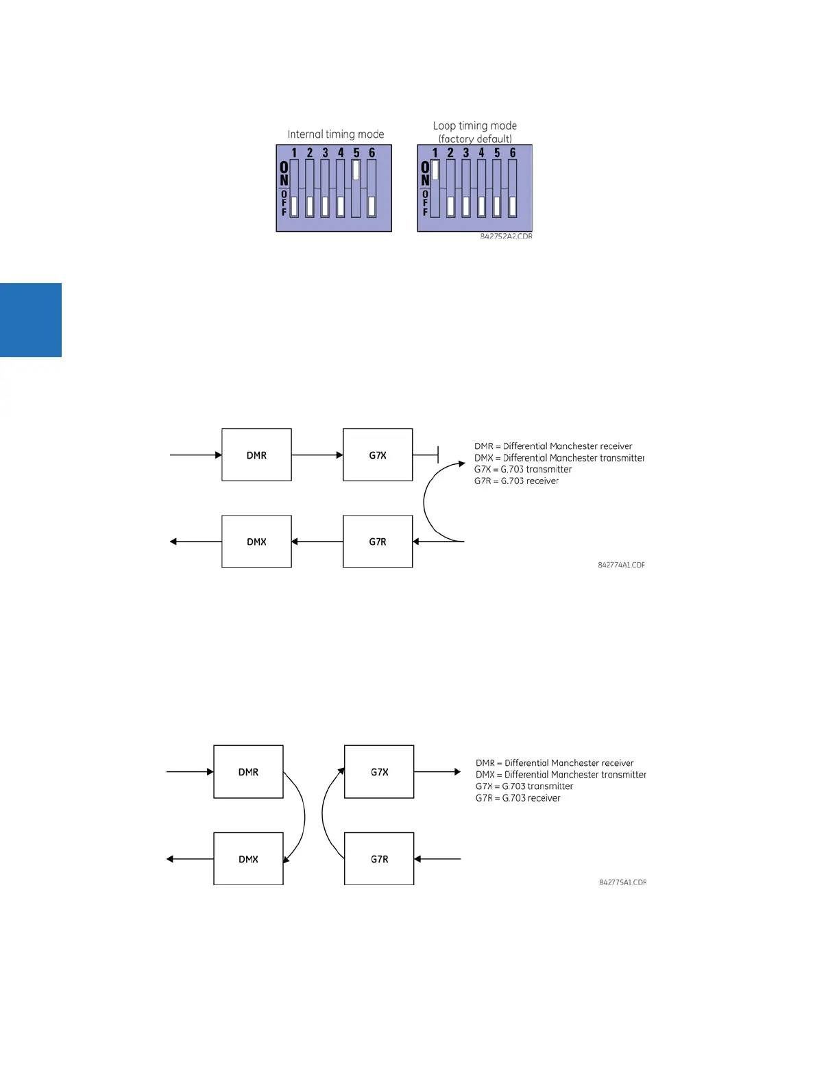
3.4.3.5 G.703 test modes
In minimum remote loopback mode, the multiplexer is enabled to return the data from the external interface without any
processing to assist in diagnosing G.703 line-side problems irrespective of clock rate. Data enters from the G.703 inputs,
passes through the data stabilization latch that also restores the proper signal polarity, passes through the multiplexer and
then returns to the transmitter. The differential received data is processed and passed to the G.703 transmitter module
after which point the data is discarded. The G.703 receiver module is fully functional and continues to process data and
passes it to the differential Manchester transmitter module. Since timing is returned as it is received, the timing source is
expected to be from the G.703 line side of the interface.
Figure 3-38: G.703 minimum remote loopback mode
In dual loopback mode, the multiplexers are active and the functions of the circuit are divided into two with each receiver/
transmitter pair linked together to deconstruct and then reconstruct their respective signals. Differential Manchester data
enters the Differential Manchester receiver module and then is returned to the differential Manchester transmitter module.
Likewise, G.703 data enters the G.703 receiver module and is passed through to the G.703 transmitter module to be
returned as G.703 data. Because of the complete split in the communications path and because, in each case, the clocks
are extracted and reconstructed with the outgoing data, in this mode there must be two independent sources of timing.
One source lies on the G.703 line side of the interface while the other lies on the differential Manchester side of the
interface.
Figure 3-39: G.703 dual loopback mode