6-16 L90 LINE CURRENT DIFFERENTIAL SYSTEM – INSTRUCTION MANUAL
METERING CHAPTER 6: ACTUAL VALUES
6
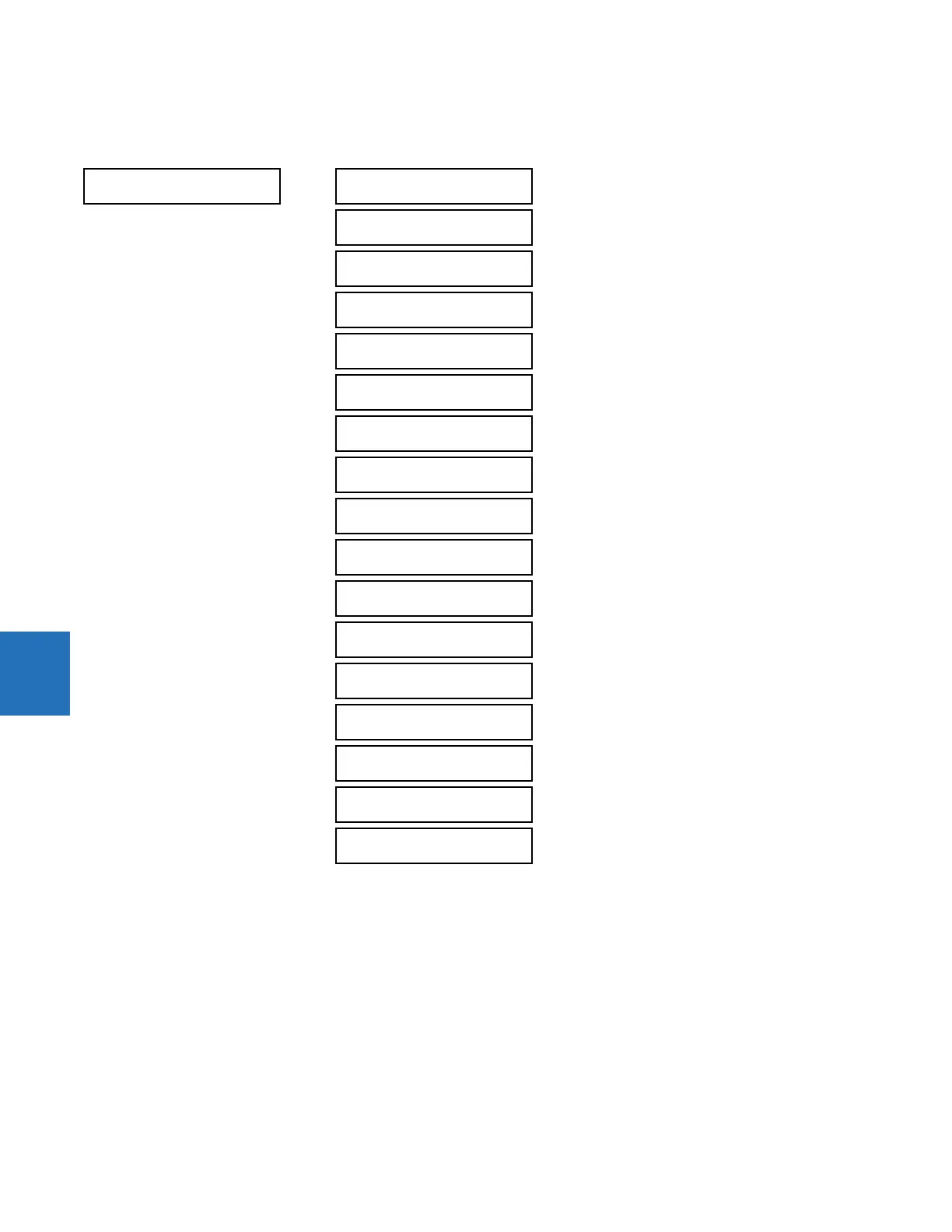
6.4.2 Differential current
ACTUAL VALUES METERING 87L DIFFERENTIAL CURRENT
The metered current values display for all line terminals in fundamental phasor form. All angles are shown with respect to
the reference common for all L90 devices; that is, frequency, source currents, and voltages. The metered primary
differential and restraint currents display for the local relay.
Terminal 1 refers to the communication channel 1 interface to a remote L90 at terminal 1. Terminal 2 refers to the
communication channel 2 interface to a remote L90 at terminal 2.
87L DIFFERENTIAL
CURRENT
LOCAL IA:
0.000 A 0.0°
LOCAL IB:
0.000 A 0.0°
LOCAL IC:
0.000 A 0.0°
TERMINAL 1 IA:
0.000 A 0.0°
TERMINAL 1 IB:
0.000 A 0.0°
TERMINAL 1 IC:
0.000 A 0.0°
TERMINAL 2 IA:
0.000 A 0.0°
TERMINAL 2 IB:
0.000 A 0.0°
TERMINAL 2 IC:
0.000 A 0.0°
IA DIFF. CURRENT:
0.000 A 0.0°
IA RESTR. CURRENT:
0.000 A
IB DIFF. CURRENT:
0.000 A 0.0°
IB RESTR. CURRENT:
0.000 A
IC DIFF. CURRENT:
0.000 A 0.0°
IC RESTR. CURRENT:
0.000 A
IG DIFF. CURRENT:
0.000 A 0.0°
IG RESTR. CURRENT:
0.000 A
 Loading...