5-324 L90 LINE CURRENT DIFFERENTIAL SYSTEM – INSTRUCTION MANUAL
CONTROL ELEMENTS CHAPTER 5: SETTINGS
5
DIR POWER 1 CALIBRATION — This setting allows the relay characteristic angle to change in steps of 0.05°. This is useful
when a small difference in VT and CT angular errors is to be compensated to permit more sensitive settings. This setting
virtually enables calibration of the directional power function in terms of the angular error of applied VTs and CTs. The
element responds to the sum of the
DIR POWER 1 RCA and DIR POWER 1 CALIBRATION settings.
DIR POWER 1 STG1 SMIN — This setting specifies the minimum power as defined along the relay characteristic angle (RCA)
for the stage 1 of the element. The positive values imply a shift towards the operate region along the RCA line; the negative
values imply a shift towards the restrain region along the RCA line. See the Directional Power Sample Applications figure
for details. Together with the RCA, this setting enables a wide range of operating characteristics. This setting applies to
three-phase power and is entered in per-unit (pu) values. The base quantity is 3 x VT pu base x CT pu base.
For example, a setting of 2% for a 200 MW machine is 0.02 × 200 MW = 4 MW. If 13.8kV is line voltage and 10 kA is a
primary CT current, the source pu quantity is 239 MVA, and thus, SMIN needs to be set at 4 MW / 239 MVA = 0.0167 pu ≈
0.017 pu. If the reverse power application is considered, RCA = 180° and SMIN = 0.017 pu.
The element drops out if the magnitude of the positive-sequence current becomes virtually zero, that is, it drops below the
cutoff level.
DIR POWER 1 STG1 DELAY — This setting specifies a time delay for stage 1. For reverse power or low forward power
applications for a synchronous machine, stage 1 is typically applied for alarming and stage 2 for tripping.
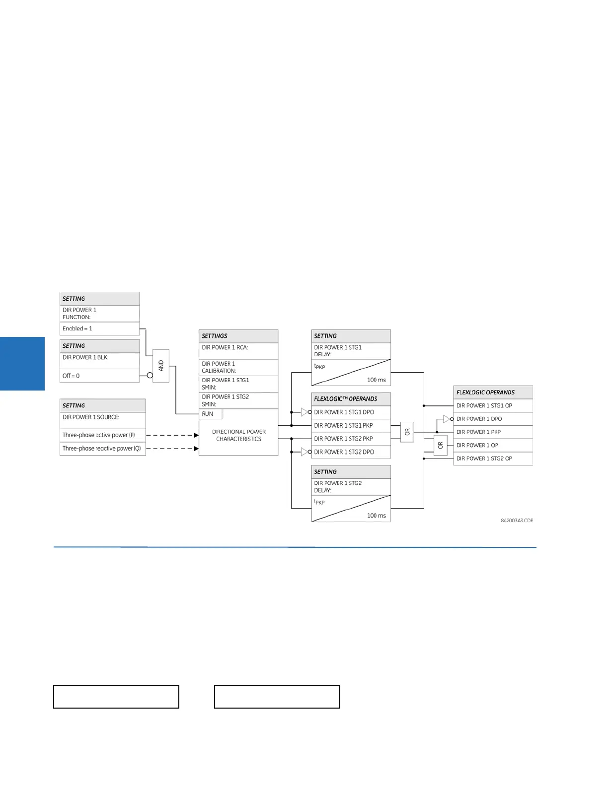
Figure 5-184: Sensitive directional power logic
5.8 Control elements
5.8.1 Overview
Control elements are used for control rather than protection. See the Introduction to Elements section at the beginning of
this chapter for information.
5.8.2 Trip bus
SETTINGS CONTROL ELEMENTS TRIP BUS TRIP BUS 1(6)
TRIP BUS 1
TRIP BUS 1
FUNCTION: Disabled
Range: Enabled, Disabled