5-350 L90 LINE CURRENT DIFFERENTIAL SYSTEM – INSTRUCTION MANUAL
CONTROL ELEMENTS CHAPTER 5: SETTINGS
5
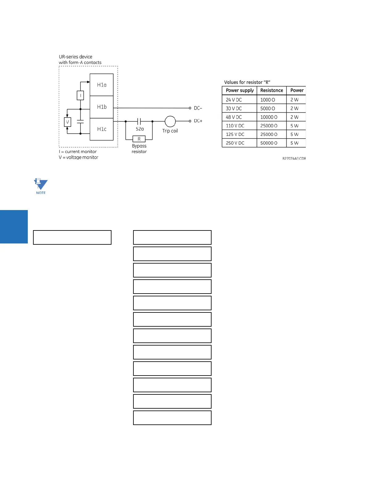
Figure 5-200: Trip circuit example 2
5.8.10 Digital counters
SETTINGS CONTROL ELEMENTS DIGITAL COUNTERS COUNTER 1(8)
The wiring connection for two examples above is applicable to both form-A contacts with voltage monitoring and
solid-state contact with voltage monitoring.
COUNTER 1
COUNTER 1
FUNCTION: Disabled
Range: Disabled, Enabled
COUNTER 1 NAME:
Counter 1
Range: up to 12 alphanumeric characters
COUNTER 1 UNITS: Range: up to six alphanumeric characters
COUNTER 1 PRESET:
0
Range: –2,147,483,648 to +2,147,483,647
COUNTER 1 COMPARE:
0
Range: –2,147,483,648 to +2,147,483,647
COUNTER 1 UP:
Off
Range: FlexLogic operand
COUNTER 1 DOWN:
Off
Range: FlexLogic operand
COUNTER 1 BLOCK:
Off
Range: FlexLogic operand
CNT1 SET TO PRESET:
Off
Range: FlexLogic operand
COUNTER 1 RESET:
Off
Range: FlexLogic operand
COUNT1 FREEZE/RESET:
Off
Range: FlexLogic operand
COUNT1 FREEZE/COUNT:
Off
Range: FlexLogic operand