CHAPTER 3: INSTALLATION PILOT CHANNEL COMMUNICATIONS
L90 LINE CURRENT DIFFERENTIAL SYSTEM – INSTRUCTION MANUAL 3-39
3
3.4.4 RS422 interface
3.4.4.1 Description
There are three RS422 inter-relay communications modules available: single-channel RS422 (module 7T), dual-channel
RS422 (module 7W), and dual-channel dual-clock RS422 (module 7V). The modules can be configured to run at 64 or
128 kbps. AWG 24 twisted shielded pair cable is recommended for external connections. These modules are protected by
optically-isolated surge suppression devices.
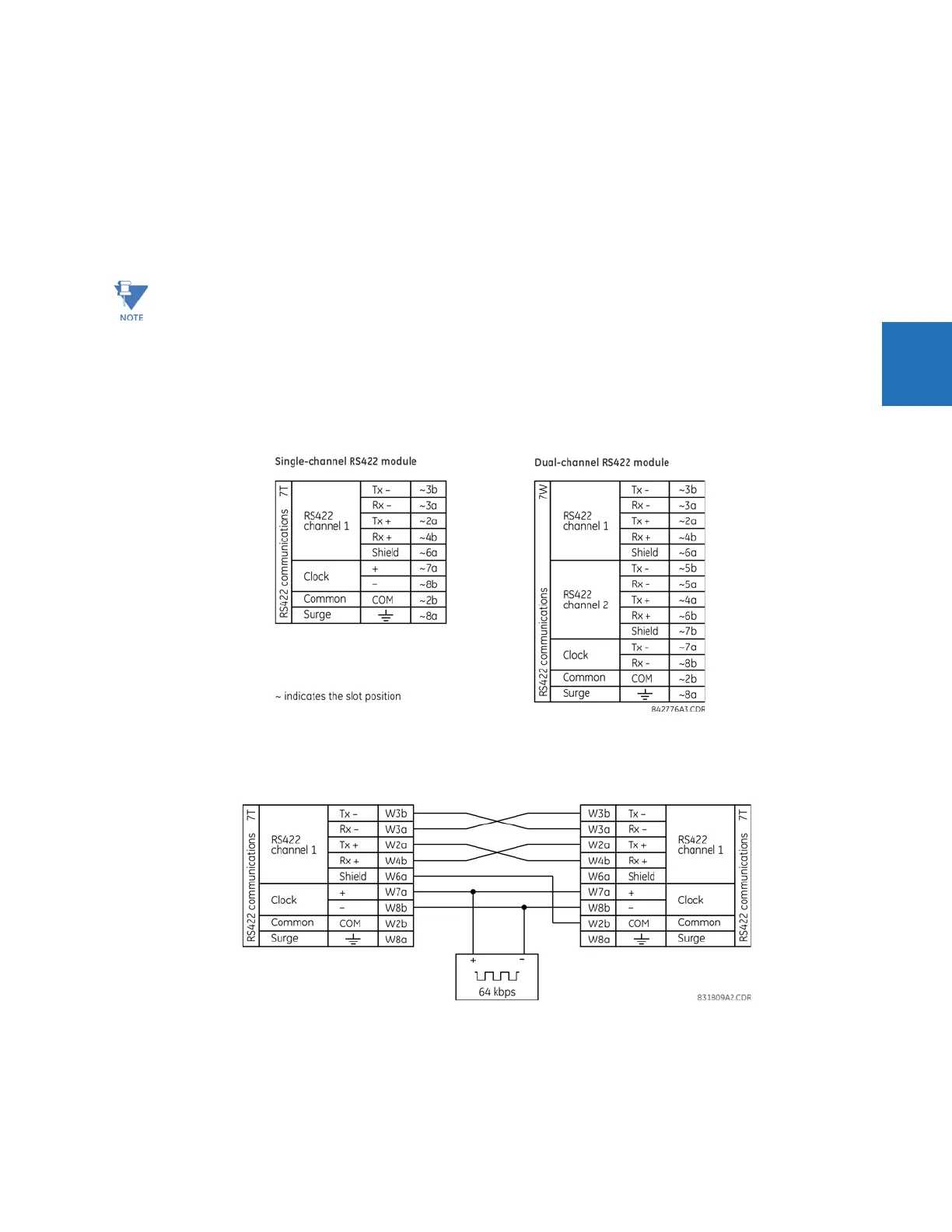
The shield pins (6a and 7b) are connected internally to the ground pin (8a). Proper shield termination is as follows:
• Site 1 — Terminate shield to pins 6a or 7b or both
• Site 2 — Terminate shield to COM pin 2b
Match the clock terminating impedance with the impedance of the line.
Figure 3-40: RS422 interface connections
The following figure shows the typical pin interconnection between two single-channel RS422 interfaces installed in slot W.
All pin interconnections are to be maintained for a connection to a multiplexer.
Figure 3-41: Typical pin interconnection between two RS422 interfaces
3.4.4.2 Two-channel application via multiplexers
The RS422 interface can be used for single-channel or two-channel applications over SONET/SDH or multiplexed systems.
When used in single-channel applications, the RS422 interface links to higher-order systems in a typical way, observing
transmit (Tx), receive (Rx), and send timing (ST) connections. However, when used in two-channel applications, certain
The two-channel two-clock RS422 interface (module 7V) is intended for use with two independent channel banks
with two independent clocks. It is intended for situations where a single clock for both channels is not acceptable.