5-302 L90 LINE CURRENT DIFFERENTIAL SYSTEM – INSTRUCTION MANUAL
GROUPED ELEMENTS CHAPTER 5: SETTINGS
5
5.7.14 Voltage elements
5.7.14.1 Menu
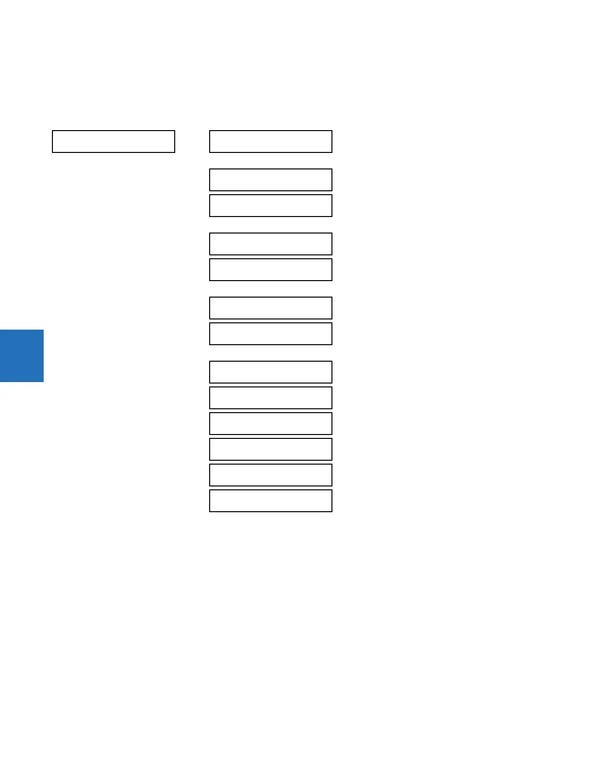
SETTINGS GROUPED ELEMENTS SETTING GROUP 1(6) VOLTAGE ELEMENTS
These protection elements can be used for a variety of applications, such as
• Undervoltage protection — For voltage sensitive loads, such as induction motors, a drop in voltage increases the
drawn current, which can cause dangerous overheating in the motor. The undervoltage protection feature can be
used to either cause a trip or generate an alarm when the voltage drops below a specified voltage setting for a
specified time delay.
• Permissive functions — The undervoltage feature can be used to block the functioning of external devices by
operating an output relay when the voltage falls below the specified voltage setting. The undervoltage feature can
also be used to block the functioning of other elements through the block feature of those elements.
• Source transfer schemes — In the event of an undervoltage, a transfer signal can be generated to transfer a load
from its normal source to a standby or emergency power source.
The undervoltage elements can be programmed to have a definite time delay characteristic. The definite time curve
operates when the voltage drops below the pickup level for a specified period of time. The time delay is adjustable from 0
to 600.00 seconds in steps of 0.01. The undervoltage elements can also be programmed to have an inverse time delay
characteristic.
VOLTAGE ELEMENTS
PHASE
UNDERVOLTAGE1
See below
PHASE
UNDERVOLTAGE3
PHASE
OVERVOLTAGE1
See page 5-304
PHASE
OVERVOLTAGE3
NEUTRAL OV1
See page 5-305
NEUTRAL OV3
AUXILIARY UV1
See page 5-306
AUXILIARY UV3
AUXILIARY OV1
See page 5-307
AUXILIARY OV2
VOLTS/HZ 1
See page 5-308
VOLTS/HZ 2
COMPENSATED
OVERVOLTAGE
See page 5-312