5-306 L90 LINE CURRENT DIFFERENTIAL SYSTEM – INSTRUCTION MANUAL
GROUPED ELEMENTS CHAPTER 5: SETTINGS
5
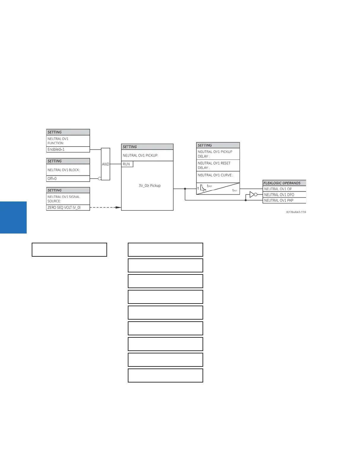
There are three neutral overvoltage elements available. The neutral overvoltage element can be used to detect
asymmetrical system voltage condition due to a ground fault or to the loss of one or two phases of the source. The
element responds to the system neutral voltage (3V_0), calculated from the phase voltages. The nominal secondary
voltage of the phase voltage channels entered under
SETTINGS SYSTEM SETUP AC INPUTS VOLTAGE BANK PHASE
VT SECONDARY
is the p.u. base used when setting the pickup level.
The neutral overvoltage element can provide a time-delayed operating characteristic versus the applied voltage (initialized
from FlexCurves A, B, or C) or be used as a definite time element. The
NEUTRAL OV1 PICKUP DELAY setting applies only if the
NEUTRAL OV1 CURVE setting is “Definite Time.” The source assigned to this element must be configured for a phase VT.
VT errors and normal voltage unbalance must be considered when setting this element. This function requires the VTs to
be wye-connected.
Figure 5-170: Neutral overvoltage1 logic
5.7.14.5 Auxiliary undervoltage (ANSI 27X, IEC PTUV)
SETTINGS GROUPED ELEMENTS SETTING GROUP 1(6) VOLTAGE ELEMENTS AUXILIARY UV1(3)
The L90 contains one auxiliary undervoltage element for each VT bank. This element monitors undervoltage conditions of
the auxiliary voltage.
The
AUX UV1 PICKUP selects the voltage level at which the time undervoltage element starts timing. The nominal secondary
voltage of the auxiliary voltage channel entered under
SETTINGS SYSTEM SETUP AC INPUTS VOLTAGE BANK X5
AUXILIARY VT X5 SECONDARY
is the per-unit base used when setting the pickup level.
AUXILIARY UV1
AUX UV1
FUNCTION: Disabled
Range: Disabled, Enabled
AUX UV1 SIGNAL
SOURCE: SRC 1
Range: SRC 1, SRC 2, SRC 3, SRC 4
AUX UV1 PICKUP:
0.700 pu
Range: 0.004 to 3.000 pu in steps of 0.001
AUX UV1 CURVE:
Definite Time
Range: Definite Time, Inverse Time
AUX UV1 DELAY:
1.00 s
Range: 0.00 to 600.00 s in steps of 0.01
AUX UV1 MINIMUM:
VOLTAGE: 0.100 pu
Range: 0.000 to 3.000 pu in steps of 0.001
AUX UV1 BLOCK:
Off
Range: FlexLogic operand
AUX UV1 TARGET:
Self-reset
Range: Self-reset, Latched, Disabled
AUX UV1 EVENTS:
Disabled
Range: Disabled, Enabled

 Loading...


