10-10 L90 LINE CURRENT DIFFERENTIAL SYSTEM – INSTRUCTION MANUAL
OVERVIEW CHAPTER 10: THEORY OF OPERATION
10
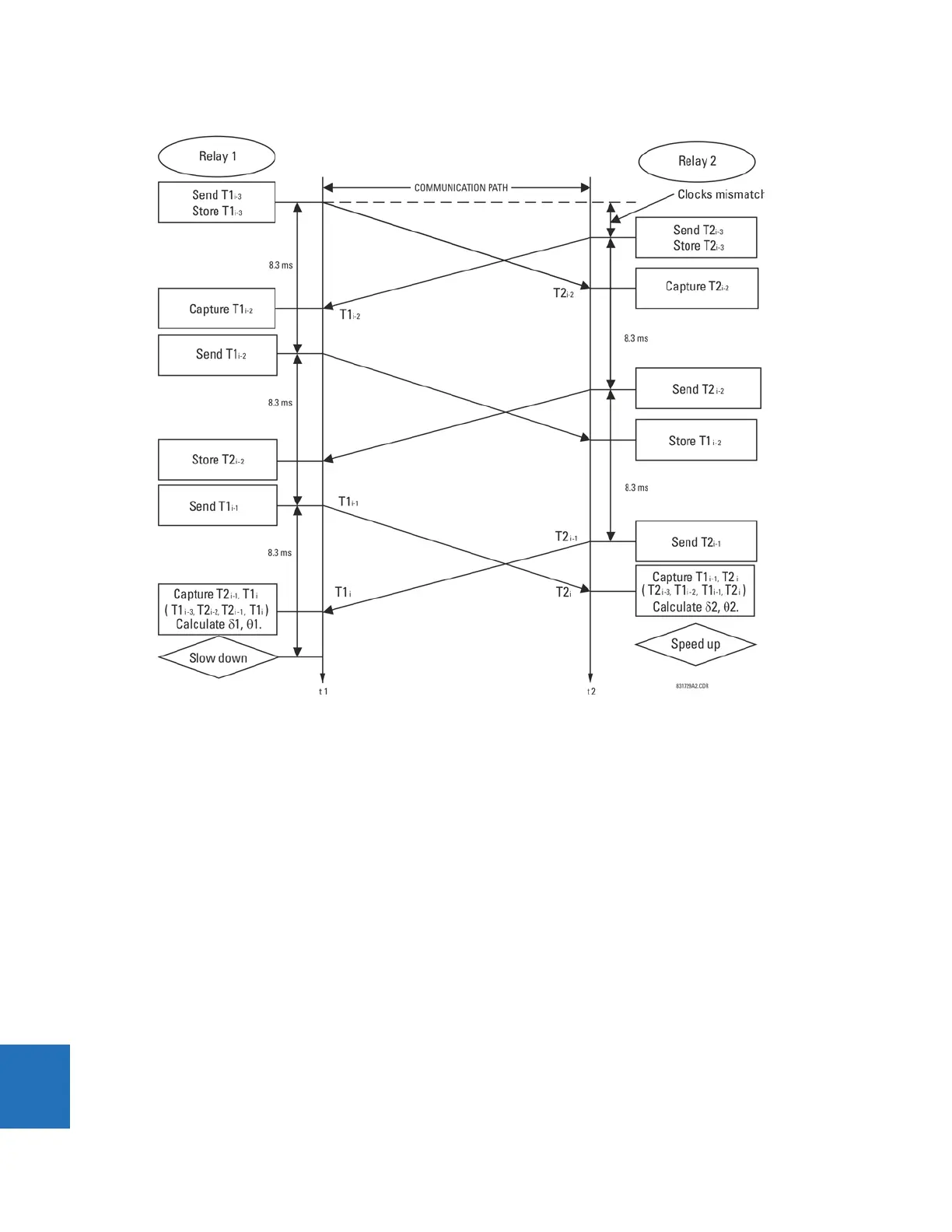
Figure 10-2: Round-trip delay and clock-offset computation for time stamps
10.1.12 Phase locking filter
Filters are used in the phase locked loop to assure stability, to reduce phase and frequency noise. This is well-known
technology. The primary feedback mechanism shown in the Loop Filter Block Diagram is phase angle information through
the well-known proportional plus integral (PI) filter (the Z in the diagram refers to a unit delay, and 1 / (Z – 1) represents a
simple digital first order integrator). This loop is used to provide stability and zero steady state error.
A PI filter has two time parameters that determine dynamic behavior: the gain for the proportional term and the gain for
the integral. Depending on the gains, the transient behavior of the loop can be underdamped, critically damped, or over
damped. For this application, critically damped is a good choice.
This sets a constraint relating the two parameters. A second constraint is derived from the desired time constants of the
loop. By considering the effects of both phase and frequency noise in this application, it can be shown that optimum
behavior results with a certain proportion between phase and frequency constraints.
A secondary input is formed through the frequency deviation input of the filter. Whenever frequency deviation information
is available, it is used for this input; otherwise, the input is zero. Because frequency is the derivative of phase information,
the appropriate filter for frequency deviation is an integrator, which is combined with the integrator of the PI filter for the
phase. It is very important to combine these two integrators into a single function because it can be shown if two separate
integrators are used, they can drift in opposite directions into saturation, because the loop would only drive their sum to
zero.