3-14 L90 LINE CURRENT DIFFERENTIAL SYSTEM – INSTRUCTION MANUAL
WIRING CHAPTER 3: INSTALLATION
3
An LED on the front of the control power module shows the status of the power supply, as outlined in the table.
Table 3-2: Power supply LED on front panel
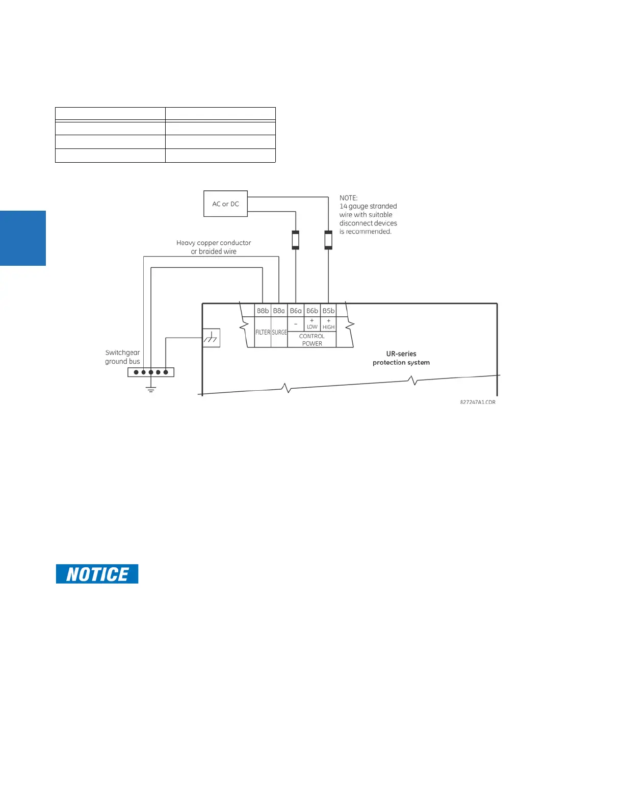
Figure 3-13: Control power connection
3.3.4 CT/VT modules
The CT and VT inputs are analog current transformer and voltage transformer signals used to monitor AC power lines. The
UR-series relays support 1 A and 5 A CTs.
A CT/VT module can have current or voltage inputs on channels 1 through 4 inclusive, or channels 5 through 8 inclusive.
Channels 1 and 5 are intended for connection to phase A, and are labelled as such in the relay. Likewise, channels 2 and 6
are intended for connection to phase B, and channels 3 and 7 are intended for connection to phase C.
Channels 4 and 8 are intended for connection to a single-phase source. For voltage inputs, these channels are labelled as
auxiliary voltage (VX). For current inputs, these channels are intended for connection to a CT between system neutral and
ground, and are labelled as ground current (IG).
To connect the module, size 12 American Wire Gauge (AWG) is used commonly; the maximum size is 10 AWG.
CT/VT modules can be ordered with a standard ground current input that is the same as the phase current input. Each AC
current input has an isolating transformer and an automatic shorting mechanism that shorts the input when the module is
withdrawn from the chassis. There are no internal ground connections on the current inputs. Current transformers with 1
to 50000 A primaries and 1 A or 5 A secondaries can be used.
These modules have enhanced diagnostics that can automatically detect CT/VT hardware failure and take the relay out of
service.
CT connections for both ABC and ACB phase rotations are identical, as shown in the Typical Wiring Diagram.
LED indication Power supply
Continuous on OK
On/off cycling Failure
Off Failure or no power
Verify that the connection made to the relay terminals for nominal current of 1 A or 5 A matches the
secondary rating of the connected CTs. Unmatched CTs can result in equipment damage or
inadequate protection.