CHAPTER 5: SETTINGS SYSTEM SETUP
L90 LINE CURRENT DIFFERENTIAL SYSTEM – INSTRUCTION MANUAL 5-167
5
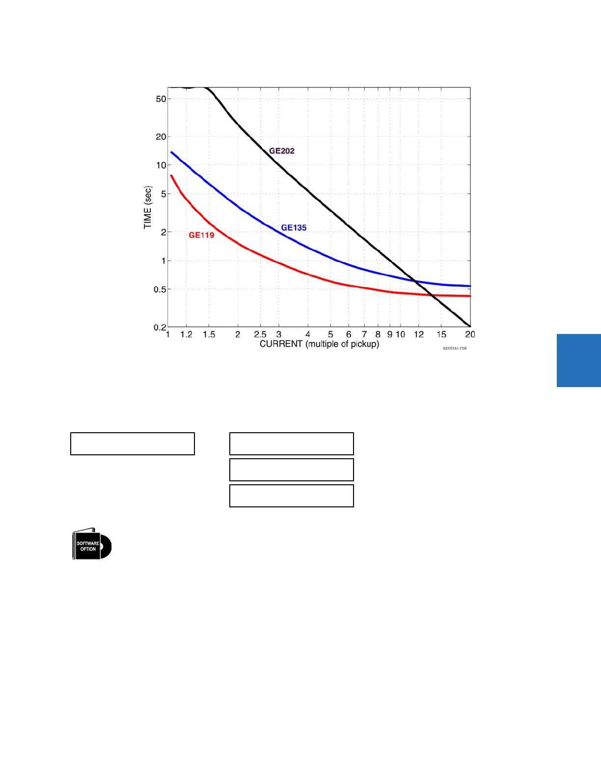
Figure 5-83: Recloser curves GE119, GE135, and GE202
5.5.8 Phasor Measurement Unit
5.5.8.1 Menu
SETTINGS SYSTEM SETUP PHASOR MEASUREMENT UNIT
5.5.8.2 UR synchrophasor implementation
Phasors are used in protection relays. When these phasors are referenced to a common time base, they are referred to as
synchrophasors. A vastly improved method for tracking power system dynamic phenomena for power system monitoring,
protection, operation, and control can be realized when synchrophasors from different locations within the power system
are networked to a central location.
The L90 offers PMU features over two communication standards, IEC 61850-90-5 and IEEE C37.118. The figure shows
complete synchrophasor implementation.
PHASOR MEASUREMENT
UNIT
PHASOR MEASUREMENT
UNIT 1
See below
PMU AGGREGATOR 1
See page 5-184
IEC 90-5 MSVCB
CONFIGURATION
See page 5-186
The L90 is provided with an optional Phasor Measurement Unit (PMU) feature. This feature is specified as a
software option at the time of ordering. The number of PMUs available also depends on this option. Using the
order code for your device, see the order codes in chapter 2 for details.