CHAPTER 8: APPLICATION OF SETTINGS CURRENT DIFFERENTIAL (87L) SETTINGS
L90 LINE CURRENT DIFFERENTIAL SYSTEM – INSTRUCTION MANUAL 8-9
8
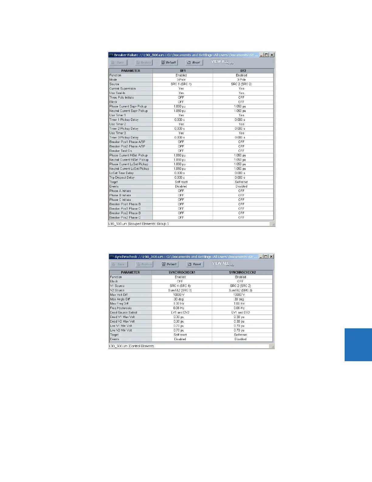
For synchrocheck 1 and 2, make the following settings changes.
8.2.8 Distributed bus protection
In some cases, buses of the same substation are located far from each other or even separated by the line. In these cases,
it is challenging to apply conventional bus protection because of the CT cable length. In other cases, there are no CTs
available on the line side of the line to be protected. Taking full advantage of L90 capability to support up to four CTs
connected directly, the relay can be applied to protect both line and buses as shown in the figure. Proper CT/VT modules
must be ordered for such applications. The varying CT ratios at the breakers can be compensated locally by using the
sources mechanism and with the CT TAP settings between remote relays. If more than four but less than eight CTs are to be
connected to the L90 at one bus, the three-terminal system can be applied, provided that the user does not exceed a total
of 12 CTs.