EasyManuals Logo

GE L90 User Manual

GE L90
900 pages
To Next Page IconTo Next Page
To Previous Page IconTo Previous Page
Page #558 background imageLoading...
Page #558 background image
5-334 L90 LINE CURRENT DIFFERENTIAL SYSTEM – INSTRUCTION MANUAL
CONTROL ELEMENTS CHAPTER 5: SETTINGS
5
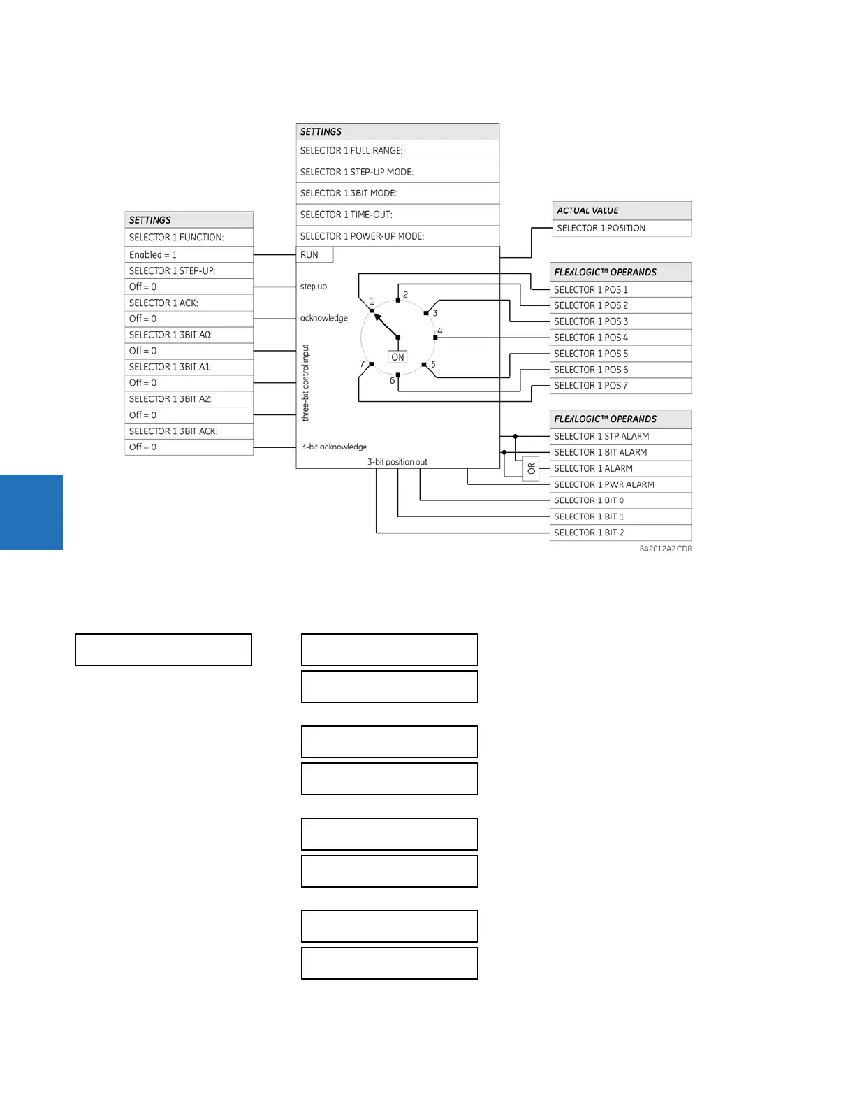
Figure 5-190: Selector switch logic
5.8.5 Trip output
SETTINGS  CONTROL ELEMENTS  TRIP OUTPUT
TRIP OUTPUT
TRIP MODE:
Disabled
Range: Disabled, 3 Pole Only, 3 Pole & 1 Pole
TRIP 3-POLE INPUT1:
Off
Range: FlexLogic operand
TRIP 3-POLE INPUT6:
Off
Range: FlexLogic operand
TRIP 1-POLE INPUT1:
Off
Range: FlexLogic operand
TRIP 1-POLE INPUT6:
Off
Range: FlexLogic operand
TRIP RECLOSE INPUT1:
Off
Range: FlexLogic operand
TRIP RECLOSE INPUT6:
Off
Range: FlexLogic operand
TRIP SEAL-IN DELAY:
0.000 s
Range: 0 to 65.535 s in steps of 0.001

Table of Contents

Questions and Answers:

Question and Answer IconNeed help?

Do you have a question about the GE L90 and is the answer not in the manual?

GE L90 Specifications

General IconGeneral
CommunicationEthernet, Serial
MountingPanel Mount
Frequency50/60 Hz
InputsDigital, Analog
OutputsRelay
ControlLocal, Remote
Communication InterfaceIEC 61850, DNP3, Modbus
Protection FunctionsDifferential, Ground Fault
Standards ComplianceIEC, IEEE

Related product manuals