CHAPTER 5: SETTINGS CONTROL ELEMENTS
L90 LINE CURRENT DIFFERENTIAL SYSTEM – INSTRUCTION MANUAL 5-325
5
The trip bus element allows aggregating outputs of protection and control elements without using FlexLogic and assigning
them a simple and effective manner. Each trip bus can be assigned for either trip or alarm actions. Simple trip conditioning
such as latch, delay, and seal-in delay are available.
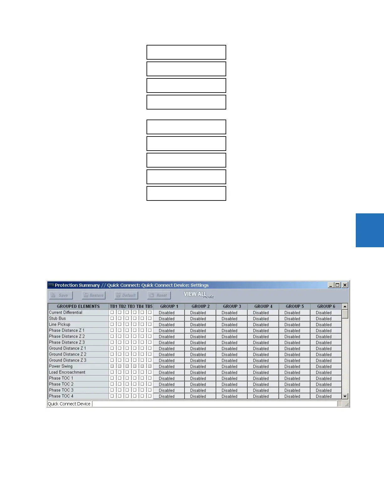
The easiest way to assign element outputs to a trip bus is through the EnerVista software under Settings > Protection
Summary. Navigate to a specific protection or control protection element and check the bus box by hovering over the
blank check box and selecting an option that displays. Once the required element is selected for a specific bus, a list of
element operate-type operands are displayed and can be assigned to a trip bus. If more than one operate-type operand is
required, it can be assigned directly from the trip bus menu.
Figure 5-185: Trip bus fields in the protection summary
The following settings are available.
TRIP BUS 1 BLOCK — The trip bus output is blocked when the operand assigned to this setting is asserted.
TRIP BUS 1 PICKUP DELAY — This setting specifies a time delay to produce an output depending on how output is used.
TRIP BUS 1 BLOCK:
Off
Range: FlexLogic operand
TRIP BUS 1 PICKUP
DELAY: 0.00 s
Range: 0.00 to 600.00 s in steps of 0.01
TRIP BUS 1 RESET
DELAY: 0.00 s
Range: 0.00 to 600.00 s in steps of 0.01
TRIP BUS 1 INPUT 1:
Off
Range: FlexLogic operand
TRIP BUS 1 INPUT 16:
Off
Range: FlexLogic operand
TRIP BUS 1
LATCHING: Disabled
Range: Enabled, Disabled
TRIP BUS 1 RESET:
Off
Range: FlexLogic operand
TRIP BUS 1:
TARGET: Self-reset
Range: Self-reset, Latched, Disabled
TRIP BUS 1
EVENTS: Disabled
Range: Enabled, Disabled