5-326 L90 LINE CURRENT DIFFERENTIAL SYSTEM – INSTRUCTION MANUAL
CONTROL ELEMENTS CHAPTER 5: SETTINGS
5
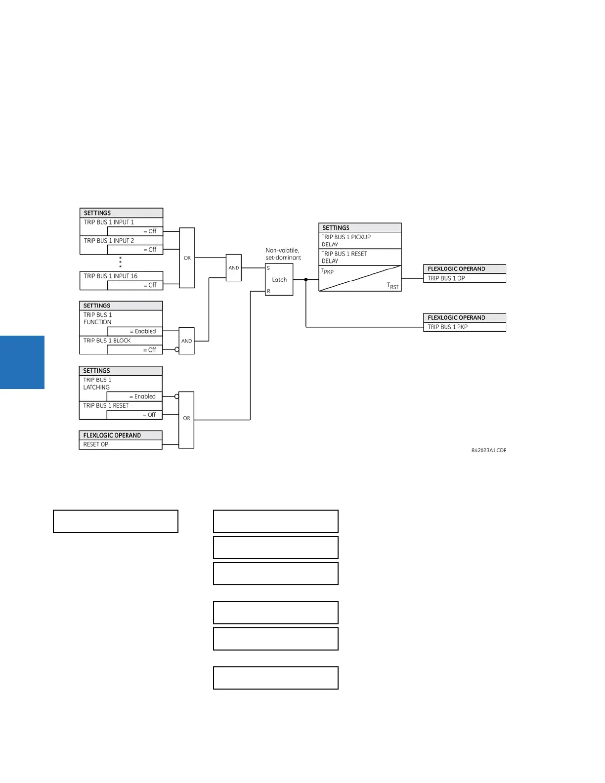
TRIP BUS 1 RESET DELAY — This setting specifies a time delay to reset an output command. Set the time delay long enough
to allow the breaker or contactor to perform a required action.
TRIP BUS 1 INPUT 1 to TRIP BUS 1 INPUT 16 — These settings select a FlexLogic operand to be assigned as an input to the trip
bus.
TRIP BUS 1 LATCHING — This setting enables or disables latching of the trip bus output. This is typically used when lockout is
required or user acknowledgement of the relay response is required.
TRIP BUS 1 RESET — The trip bus output is reset when the operand assigned to this setting is asserted. Note that the RESET OP
operand is pre-wired to the reset gate of the latch, As such, a reset command from the front panel interface or via
communications resets the trip bus output.
Figure 5-186: Trip bus logic
5.8.3 Setting groups
SETTINGS CONTROL ELEMENTS SETTING GROUPS
SETTING GROUPS
SETTING GROUPS
FUNCTION: Enabled
Range: Disabled, Enabled
SETTING GROUPS BLK:
Off
Range: FlexLogic operand
GROUP 2 ACTIVATE ON:
Off
Range: FlexLogic operand
GROUP 6 ACTIVATE ON:
Off
Range: FlexLogic operand
GROUP 1 NAME: Range: up to 16 alphanumeric characters
GROUP 6 NAME: Range: up to 16 alphanumeric characters