CHAPTER 5: SETTINGS CONTROL ELEMENTS
L90 LINE CURRENT DIFFERENTIAL SYSTEM – INSTRUCTION MANUAL 5-327
5
The setting groups menu controls the activation and deactivation of up to six possible groups of settings in the GROUPED
ELEMENTS
settings menu. The active setting group can be indicated on the front display of the UR by configuring User-
Programmable LEDs to display the state of the SETTING GROUP ACT FlexLogic operands.
SETTING GROUPS FUNCTION — When Enabled, allows setting groups other than group 1 (the default active group) to be
activated. The default setting group is forced active while the SETTING GROUPS FUNCTION setting is Disabled.
SETTING GROUPS BLK — Prevents the active setting group from changing when the selected FlexLogic operand is "On." This
can be useful in applications where it is undesirable to change the settings under certain conditions, such as during a
control sequence.
GROUP 2 ACTIVATE ON to GROUP 6 ACTIVATE ON — Selects a FlexLogic operand which, when set, makes the particular setting
group active for use by any grouped element. A priority scheme ensures that only one group is active at a given time — the
highest-numbered group that is activated by its
ACTIVATE ON parameter takes priority over the lower-numbered groups.
There is no activate on setting for group 1 (the default active group), because group 1 automatically becomes active if no
other group is active.
SETTING GROUP 1 NAME to SETTING GROUP 6 NAME — Allows the user to assign a name to each of the six settings groups.
Once programmed, this name appears on the second line of the
GROUPED ELEMENTS SETTING GROUP 1(6) menu display.
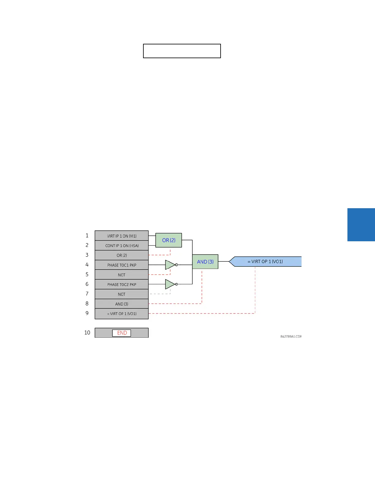
The relay can be set up via a FlexLogic equation to receive requests to activate or de-activate a particular non-default
settings group. The following FlexLogic equation (see the following figure) illustrates requests via remote communications
(for example,
VIRTUAL INPUT 1 ON) or from a local contact input (for example, CONTACT IP 1 ON) to initiate the use of a particular
settings group, and requests from several overcurrent pickup measuring elements to inhibit the use of the particular
settings group. The assigned
VIRTUAL OUTPUT 1 operand is used to control the “On” state of a particular settings group.
Figure 5-187: Example of FlexLogic control of a setting group
A setting group selection can also be made by the IEC 61850 MMS service SelectActiveSG to the control block @Master/
LLN0.SGCB. The priority scheme mentioned makes active the highest numbered group selected by SelectActiveSG or the
GROUP ACTIVATE ON settings. The SelectActiveSG selection has a default value of 1, so until a higher SelectActiveSG
selection is received, the
GROUP ACTIVATE ON settings control the active group.
The most recent SelectActiveSG selection is preserved while the UR is powered down or reset.
If it becomes necessary to cancel the SelectActiveSG selection without using a SelectActiveSG service request, change the
SETTING GROUPS FUNCTION setting to Disabled. This resets the SelectActiveSG selection to 1.
SETTING GROUP
EVENTS: Disabled
Range: Disabled, Enabled
 Loading...


