CHAPTER 5: SETTINGS GROUPED ELEMENTS
L90 LINE CURRENT DIFFERENTIAL SYSTEM – INSTRUCTION MANUAL 5-275
5
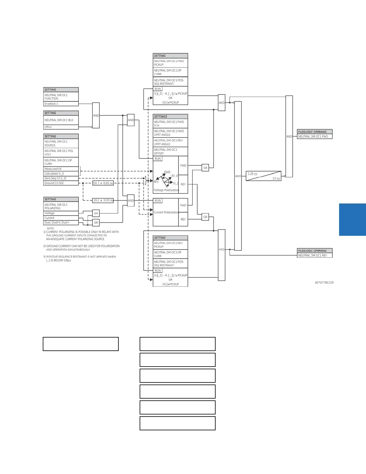
Figure 5-149: Neutral directional overcurrent logic
5.7.10 Wattmetric ground fault
5.7.10.1 Wattmetric zero-sequence directional (ANSI 32N, IEC PSDE)
SETTINGS GROUPED ELEMENTS SETTING GROUP 1(6) WATTMETRIC... WATTMETRIC GROUND FAULT 1(2)
WATTMETRIC
GROUND FAULT 1
WATTMETRIC GND FLT 1
FUNCTION: Disabled
Range: Disabled, Enabled
WATTMETRIC GND FLT 1
SOURCE: SRC 1
Range: SRC 1, SRC 2, SRC 3, SRC 4
WATTMETRIC GND FLT 1
VOLT: Calculated VN
Range: Calculated VN, Measured VX
WATTMETRIC GND FLT 1
OV PKP: 0.20 pu
Range: 0.02 to 3.00 pu in steps of 0.01
WATTMETRIC GND FLT 1
CURR: Calculated IN
Range: Calculated IN, Measured IG
WATTMETRIC GND FLT 1
OC PKP: 0.060 pu
Range: 0.002 to 30.000 pu in steps of 0.001