CHAPTER 2: PRODUCT DESCRIPTION PRODUCT DESCRIPTION
L90 LINE CURRENT DIFFERENTIAL SYSTEM – INSTRUCTION MANUAL 2-3
2
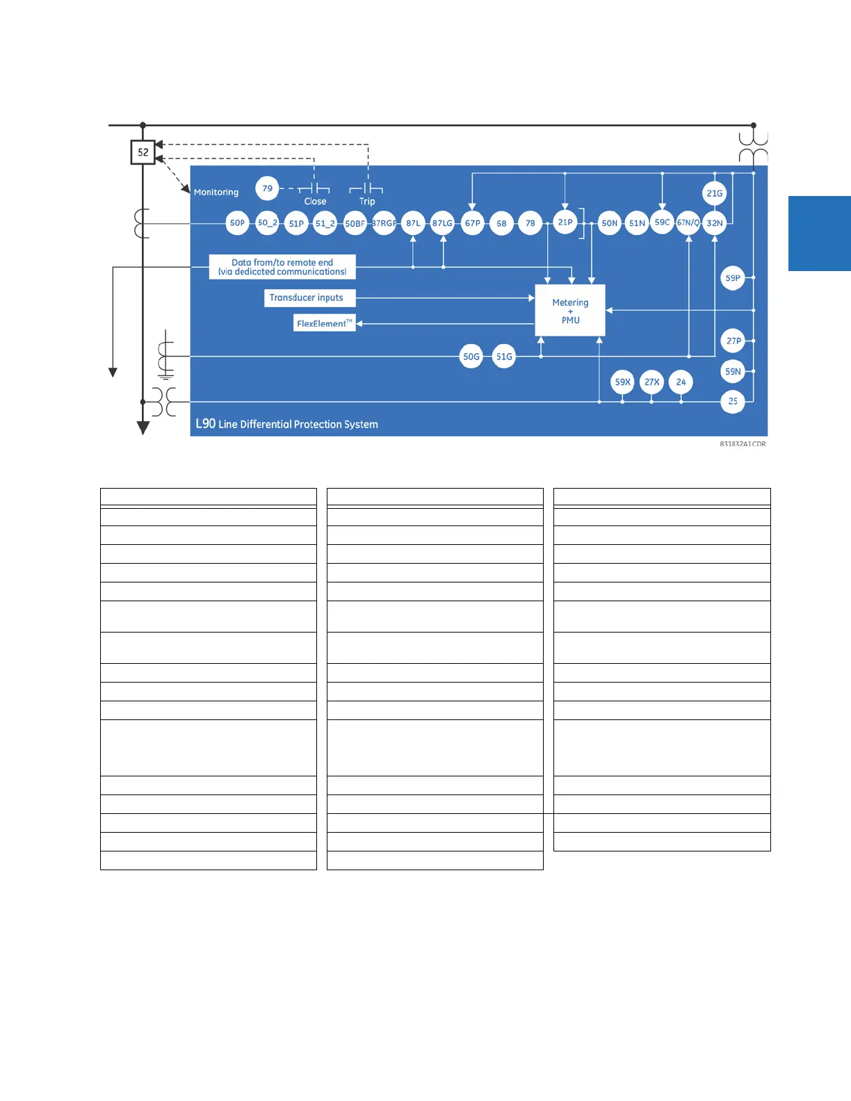
Figure 2-1: Single-line diagram
Table 2-2: Other device functions
2.1.1 Features
2.1.1.1 Line current differential
• Phase segregated, high-speed digital current differential system
• Overhead and underground AC transmission lines, series compensated lines
Function Function Function
Breaker Arcing Current (I
2
t) Fault Locator Oscillography
Breaker Control Fault Reporting Pilot Schemes
Breaker Flashover FlexElements™ (8) Setting Groups (6)
Broken Conductor Detection FlexLogic™ Equations Stub Bus
Contact Inputs (up to 120) IEC 60870-5-103 Communications Synchrophasor (PMU)
Contact Outputs (up to 72) IEC 61850 Communications Time synchronization over IRIG-B or IEEE
1588
Control Pushbuttons IEC 62351-9 Data and Communications
Security
Time Synchronization over SNTP
CT Failure Detector L90 Channel Tests Transducer Inputs/Outputs
CyberSentry™ Security Line Pickup User Definable Displays
Data Logger Load Encroachment User Programmable LEDs
Digital Counters (8) Metering: Current, Voltage, Power, Energy,
Frequency, Demand, Power Factor, 87L
current, local and remote phasors,
harmonics, THD
User Programmable Pushbuttons
Digital Elements (48) Modbus Communications User Programmable Self-Tests
Direct Inputs (8 per L90 comms channel) Modbus User Map Virtual Inputs (64)
Disconnect Switches Non-Volatile Latches Virtual Outputs (96)
DNP 3.0 or IEC 60870-5-104 protocol Non-Volatile Selector Switch VT Fuse Failure
Event Recorder Open Pole Detector