CHAPTER 6: ACTUAL VALUES METERING
L90 LINE CURRENT DIFFERENTIAL SYSTEM – INSTRUCTION MANUAL 6-25
6
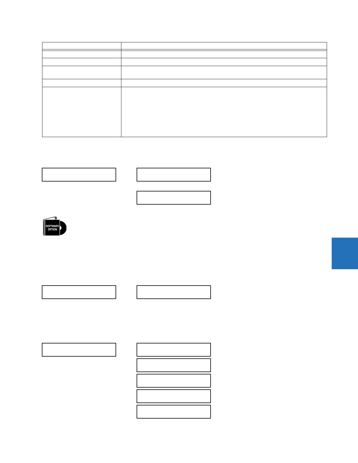
6.4.9 RxGOOSE analogs
ACTUAL VALUES METERING RxGOOSE Analogs
The RxGOOSE Analog values display in this menu. The RxGOOSE Analog values are received via IEC 61850 GOOSE
messages sent from other devices.
6.4.10 Wattmetric ground fault
ACTUAL VALUES METERING WATTMETRIC GROUND FAULT 1(2)
This menu displays the wattmetric zero-sequence directional element operating power values.
6.4.11 Phasor Measurement Unit
ACTUAL VALUES METERING PHASOR MEASURMENT UNIT PMU 1
SOURCE THD & HARMONICS BASE = 1%
SOURCE VOLTAGE V
BASE
= maximum nominal primary RMS value of the +IN and –IN inputs
SYNCHROCHECK
(Max Delta Volts)
V
BASE
= maximum primary RMS value of all the sources related to the +IN and –IN inputs
VOLTS PER HERTZ BASE = 1.00 pu
Z
BASE
Z
BASE
= PhaseVTSecondary / PhaseCTSecondary, where PhaseVTSecondary and
PhaseCTSecondary are the secondary nominal voltage and the secondary nominal current of the
distance source. In case multiple CT inputs are summed as one source current and mapped as the
distance source, use the PhaseCTSecondary value from the CT with the highest primary nominal
current.
Distance source is specified in setting under SETTINGS GROUPED ELEMENTS SETTING
GROUP 1(6) DISTANCE.
PhaseVTSecondary and PhaseCTSecondary are specified in setting under SETTINGS SYSTEM
SETUP AC INPUTS.
RxGOOSE
Analogs
RxGOOSE Analog 1
0.000
RxGOOSE Analog 32
0.000
The L90 is provided with optional GOOSE communications capability. This feature is specified as a software
option at the time of ordering. See the Order Codes section of chapter 2 for details.
WATTMETRIC
GROUND FAULT 1
WATT GND FLT 1:
0.000 W
PMU 1
PMU 1 VA:
0.000 V 0.00°
Range: Va or Vab per VT bank connection
PMU 1 VB:
0.000 V 0.00°
Range: Va or Vab per VT bank connection
PMU 1 VC:
0.000 V 0.00°
Range: Va or Vab per VT bank connection
PMU 1 VX:
0.000 V 0.00°
PMU 1 V1:
0.000 V 0.00°
Base unit Description