CHAPTER 6: ACTUAL VALUES FRONT PANEL
L90 LINE CURRENT DIFFERENTIAL SYSTEM – INSTRUCTION MANUAL 6-3
6
For status reporting, ‘On’ represents Logic 1 and ‘Off’ represents Logic 0.
6.2 Front panel
The front panel can be viewed and used in the EnerVista software, for example to view an error message displayed on the
front panel. The feature applies to the enhanced and standard front panels.
To view the front panel in EnerVista software:
1. Click Actual Values > Front Panel.
VOLTS PER HERTZ 2
RESTRICTED GROUND
FAULT CURRENTS
See page 6-27
TRANSDUCER I/O
DCMA INPUTS
See page 6-27
TRANSDUCER I/O
RTD INPUTS
See page 6-27
DISTANCE
See page 6-27
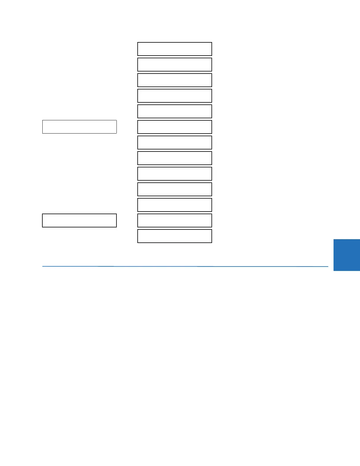
ACTUAL VALUES
RECORDS
FAULT REPORTS
See page 6-29
EVENT RECORDS
See page 6-30
OSCILLOGRAPHY
See page 6-32
DATA LOGGER
See page 6-32
PMU RECORDS
See page 6-33
MAINTENANCE
See page 6-33
ACTUAL VALUES
PRODUCT INFO
MODEL INFORMATION
See page 6-34
FIRMWARE REVISIONS
See page 6-34