CHAPTER 2: PRODUCT DESCRIPTION PILOT CHANNEL RELAYING
L90 LINE CURRENT DIFFERENTIAL SYSTEM – INSTRUCTION MANUAL 2-7
2
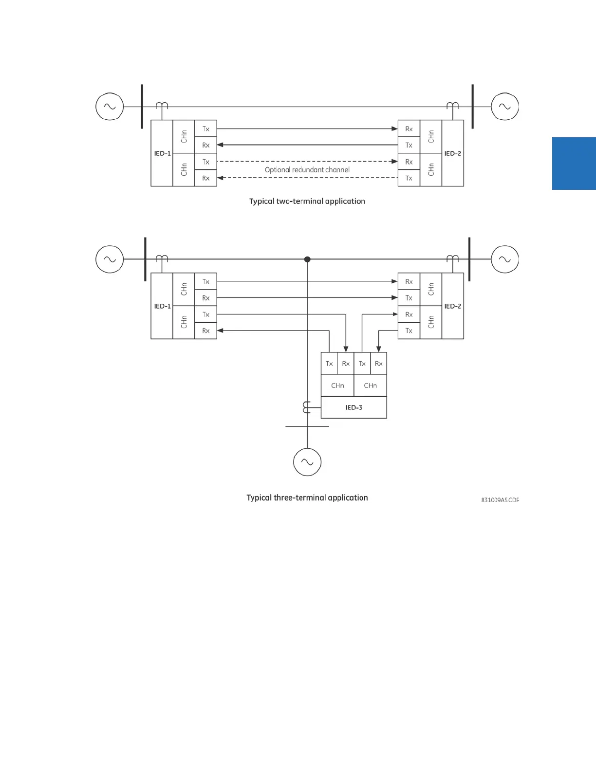
Figure 2-2: Communication paths
2.2.2 Channel monitor
The L90 has logic to detect that the communications channel is deteriorating or has failed completely. This can provide an
alarm indication and disable the current differential protection. Note that a failure of the communications from the master
to a slave does not prevent the master from performing the current differential algorithm; failure of the communications
from a slave to the master prevents the master from performing the correct current differential logic. Channel propagation
delay is being continuously measured and adjusted according to changes in the communications path. Every relay on the
protection system can be assigned a unique ID to prevent advertent loopbacks at multiplexed channels.
2.2.3 Loopback test
This option allows the user to test the relay at one terminal of the line by looping the transmitter output to the receiver
input. At the same time, the signal sent to the remote does not change. A local loopback feature is included in the relay to
simplify single ended testing.