5-312 L90 LINE CURRENT DIFFERENTIAL SYSTEM – INSTRUCTION MANUAL
GROUPED ELEMENTS CHAPTER 5: SETTINGS
5
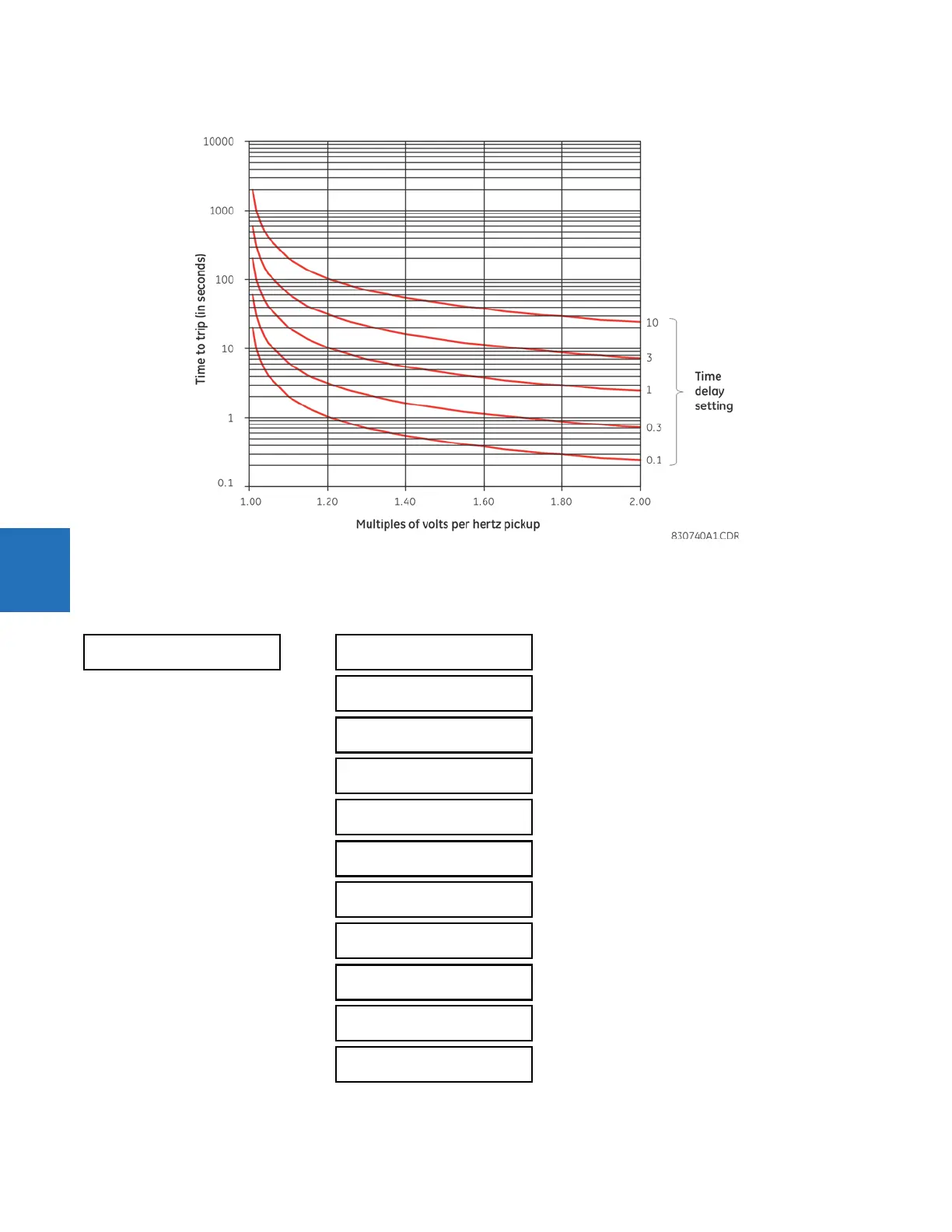
Figure 5-176: Volts-per-hertz curves, inverse curve C
5.7.14.8 Compensated overvoltage (ANSI 59C, IEC PTOV)
SETTINGS GROUPED ELEMENTS SETTING GROUP 1(6) VOLTAGE ELEMENTS COMPENSATED
OVERVOLTAGE
COMPENSATED
OVERVOLTAGE
COMPENSATED OV
FUNCTION: Disabled
Range: Disabled, Enabled
COMPENSATED OV
SOURCE: SRC 1
Range: SRC 1, SRC 2, SRC 3, SRC 4
COMPENSATED OV Zc
MAG: 2.00 ohm
Range: 0.00 to 500.00 ohms in steps of 0.01
COMPENSATED OV Zc
ANG: 90°
Range: 30 to 90° in steps of 1
COMPENSATED OV
I_1max: 0.20 pu
Range: 0.01 to 1.00 pu in steps of 0.01
COMPENSATED OV STG1
PKP: 1.300 pu
Range: 0.250 to 3.000 pu in steps of 0.01
COMPENSATED OV STG1
DELAY: 1.00 sec
Range: 0.00 to 600.00 seconds in steps of 0.01
COMPENSATED OV STG2
PKP: 1.300 pu
Range: 0.250 to 3.000 pu in steps of 0.01
COMPENSATED OV STG2
DELAY: 1.00 sec
Range: 0.00 to 600.00 seconds in steps of 0.01
COMPENSATED OV STG3
PKP: 1.300 pu
Range: 0.250 to 3.000 pu in steps of 0.01
COMPENSATED OV STG3
DELAY: 1.00 sec
Range: 0.00 to 600.00 seconds in steps of 0.01